Drawer slide rail assembly
A technology of drawers and slide rails, applied in drawers, furniture parts, household appliances, etc.
- Summary
- Abstract
- Description
- Claims
- Application Information
AI Technical Summary
Problems solved by technology
Method used
Image

Examples
Embodiment Construction
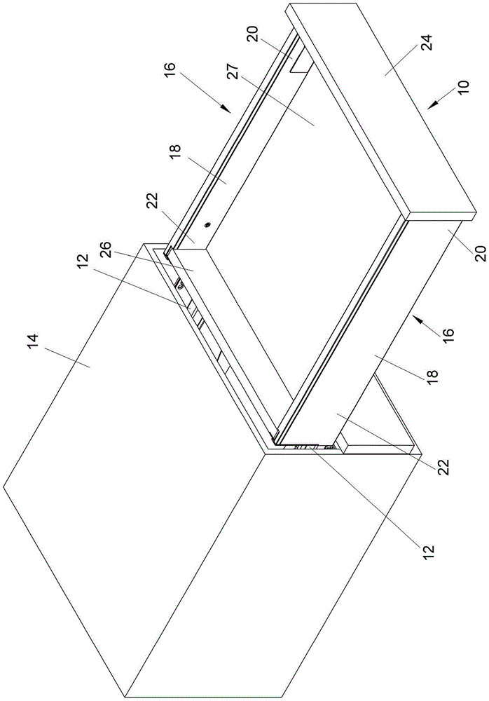
[0039] figure 1 Showing an embodiment of the present invention, a drawer 10 is installed to a cabinet body 14 by means of a pair of slide rail assemblies 12 , so that the drawer 10 can be smoothly pulled out from the cabinet body 14 or pushed into the cabinet body 14 to be closed. This drawer 10 comprises a pair of drawer supports (drawer frame) 16, each drawer support 16 comprises a drawer side wall 18, and this drawer side wall 18 comprises a front end 20 and a rear end 22, the drawer of this pair of drawer supports 16 The front end 20 of the side wall 18 is jointly connected with a front panel 24, and the rear end 22 of the drawer side wall 18 of the pair of drawer brackets 16 is jointly connected with a rear panel 26. The pair of drawer side walls 18, the front panel 24 and the rear panel The panels 26 are joined to a drawer bottom 27 to form the drawer 10 .
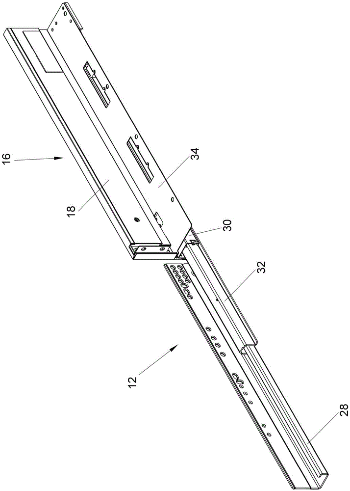
[0040] figure 2 It is shown that the sliding rail assembly 12 further includes a first rail 28 , and a second r...
PUM
 Abstract
Description
Claims
Application Information
 - R&D
- Intellectual Property
- Life Sciences
- Materials
- Tech Scout
- Unparalleled Data Quality
- Higher Quality Content
- 60% Fewer Hallucinations
Browse by: Latest US Patents, China's latest patents, Technical Efficacy Thesaurus, Application Domain, Technology Topic, Popular Technical Reports.
© 2025 PatSnap. All rights reserved.Legal|Privacy policy|Modern Slavery Act Transparency Statement|Sitemap|About US| Contact US: help@patsnap.com