
Optical cable and cable sheath peeling device

A technology of cable sheathing and stripping device, which is applied in the direction of dismantling/armoring cable equipment, fiber mechanical structure, etc., can solve the problem that the centering adjustment of the cable jacket is not convenient, the stress state is not ideal, and the working stability and stripping quality are affected. And other issues

Active Publication Date: 2010-08-25
NANJING WASIN FUJIKURA OPTICAL COMM LTD +1
View PDF3 Cites 0 Cited by
  • Summary
  • Abstract
  • Description
  • Claims
  • Application Information

AI Technical Summary

Problems solved by technology

Although this device can realize the stripping operation of the outer sheath of the cable, the centering adjustment of the cable sheath is not convenient enough, and the stress state during cutting is not ideal, thus affecting the working stability and stripping quality

Method used


Image

  • Optical cable and cable sheath peeling device
  • Optical cable and cable sheath peeling device
  • Optical cable and cable sheath peeling device

Examples


Embodiment 1

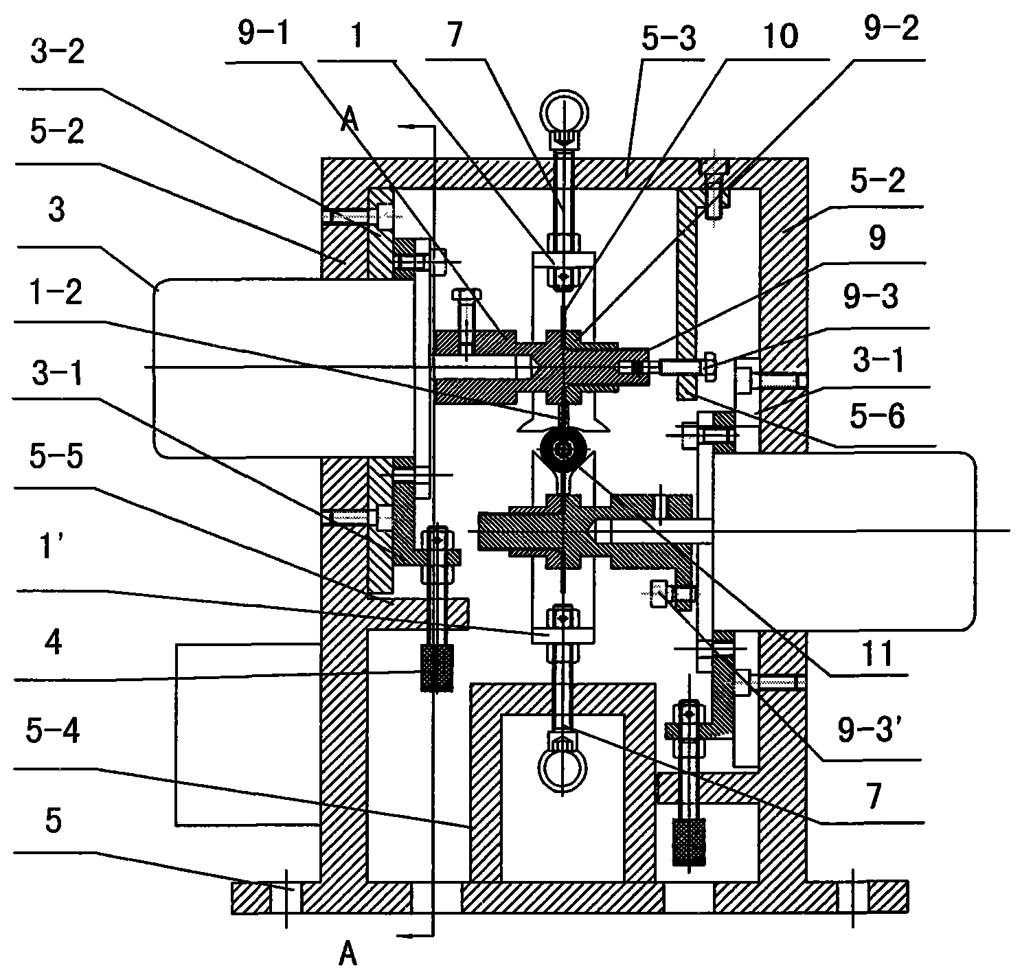
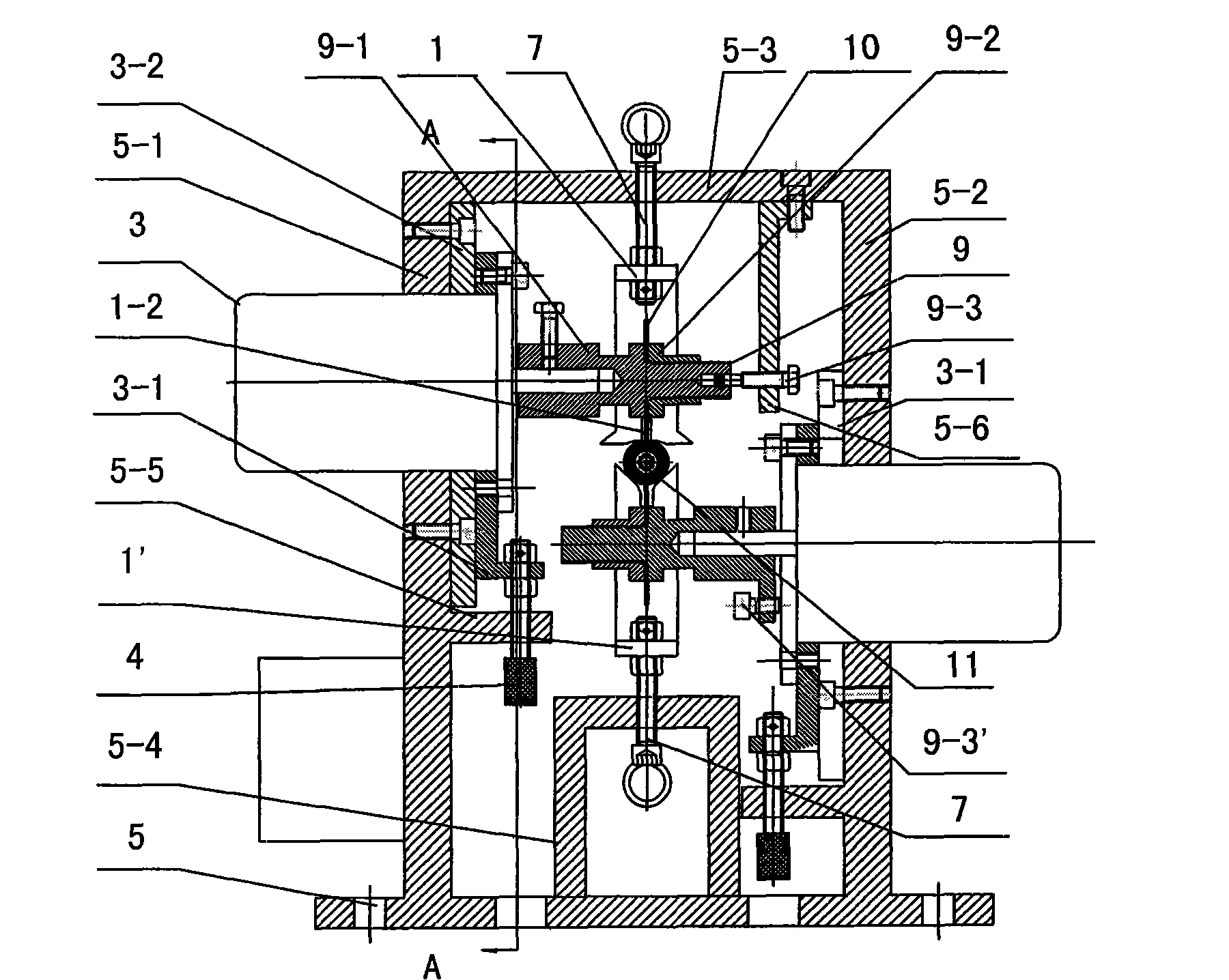
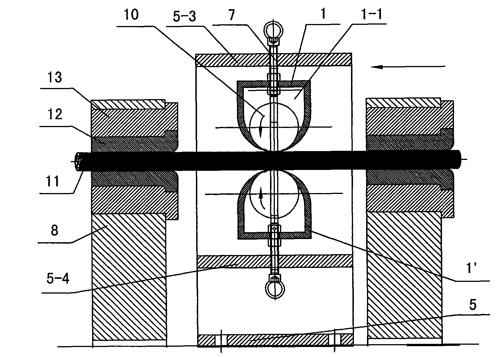
[0013] The optical cable and the cable sheath stripping device of the present embodiment are shown in Figure 1 to Figure 3, and support frame comprises the left and right vertical support 5-1,5-2 that is supported on the base plate 5, and the top of left and right vertical support is The horizontal brace 5-3 that connects it as a whole constitutes an outer frame that is a door shape as a whole, and also includes an inner frame 5-4 positioned at the middle and lower part of the outer frame. The centers of the cross brace 5-3 and the inner frame 5-3 are respectively shaped on vertical threaded holes, in which the centering bolts 7 of the upper cable clamp 1 for lifting downwards and the upper cable clamp 1' for upward support are housed respectively. By means of the centering bolt 7, the distance between the upper cable clamp 1 and the lower cable clamp 1' can be easily adjusted, so as to adapt to cables of different diameters. The upper and lower cable clamps 1, 1' middle part ...


PUM


Abstract

The invention relates to an optical cable and a cable sheath peeling device, belonging to the cable tool technology field. The support frame of the device comprises a door-shaped outer frame and an inner frame. An upper cable clamper and a lower cable clamper are respectively installed in a perpendicular screwed hole in the center of the transverse brace and the inner frame. The middle part of theclamper of the upper cable and the lower cable is provided with a relieving hole and a centering relieving hole along the axial direction of the milling cutter and the opposite ends forming a cross section are respectively provided with a clamping groove and a V-shaped groove with the arc shape. A perpendicular guide rail forming a moving pair with a motor installation seat is respectively at theupper part and the lower part in the inner side of the left vertical support and the right vertical support. A helical pair regulating the lifting of the motor installation seat is arranged at the lower end of the motor installation seat. A lockable milling fixture is sleeved in the main axle of the horizontal motor on the motor installation seat. One end of the milling fixture forms a left-and-right position screw thread fine tuning mechanism by a horizontal regulating screw. The device can effectively peel the optical cable or the cable sheath with easy operation.

Description

technical field [0001] The invention relates to a stripping tool for a coaxial cable, in particular to an optical cable and a cable sheath stripping device, belonging to the technical field of cable tools. Background technique [0002] For a long time, the stripping of wires such as optical cables and electric cables has always been a troublesome work. For this reason, people use their brains to design some special tools. For example, the Chinese patent that the application number is 02273645.X discloses a kind of cable peeling cutter, when the cable is peeled, the motor drives the rod milling cutter to rotate, and the cable is inserted into the overcoat, and the rod milling cutter cuts the cable sheath along the axial direction, and then Open the clutch to make the rotary table rotate on the support, and the rod milling cutter cuts the cable sheath along the ring direction, so that the cable sheath and the cable core are completely separated, and the cable peeling process ...

Claims


Application Information

Patent Timeline
Patent Type & Authority Patents(China)
IPC IPC(8): G02B6/44H02G1/12
Inventor 王振云戚卫
Owner NANJING WASIN FUJIKURA OPTICAL COMM LTD
Learn More