Cable laying structure

A zipline and rope technology, applied in the field of zipline laying structure, can solve the problems of easy breakage, affecting the sliding speed, inability to adjust the height and tension of the zipline, and achieves low cost, avoids relative rotation, and is suitable for popularization and use. Effect

Active Publication Date: 2017-06-13
山东维点技术有限公司
View PDF5 Cites 0 Cited by
  • Summary
  • Abstract
  • Description
  • Claims
  • Application Information

AI Technical Summary

Problems solved by technology

The tension of the zip line has special requirements, too tight is easy to break, too loose will affect the sliding speed
The middle pa

Method used


Image

  • Cable laying structure
  • Cable laying structure
  • Cable laying structure

Examples


Embodiment 2

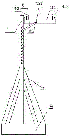
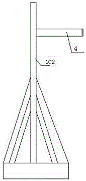
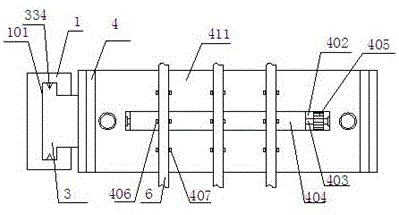
[0018] When in use, first insert the sliding block 3 on the support plate 4 into the guide groove 101, make it slide to the corresponding height that needs to be assembled, and then insert the support bar 5 into the slot 102 and the first slot 401 respectively and pass through the firm 521 is fixedly connected; rope fixing implementation 1: directly buckle the rope 6 into the corresponding first embedded buckle 407 and second embedded buckle 406 to complete the initial fixation, and then pass through the two second fastenings on the top of the cover plate 412 Part 413 is screwed into the support plate 4 to complete the fixation; rope fixing implementation 2: drive the threaded rod 403 to rotate by toggling the allocation wheel 405, and control the sliding bar 404 to slide along the direction of the allocation groove 402, so that the first on the sliding bar 404 There is a certain angle between the second buckle 406 and the first buckle 407 on the support plate 4, and the rope 6...


PUM


Abstract

The invention discloses a cable laying structure. The structure comprises a floor stand. The floor stand is arranged vertically, and the top of the floor stand is provided with a guide groove, the guide groove passes through the floor stand, and the front and rear positions of the upper portion of the floor stand are inclined provided with an inserting groove. A sliding block is arranged in the guide groove, the right end of the sliding block extends to the outer portion of the guide groove, and the right end of the sliding block is matched with a supporting plate. The front and rear positions of the supporting plate are provided with a first inserting groove which is matched with the inserting groove, and a supporting rod is arranged between the inserting groove and the first inserting groove in a matching mode. According to the cable laying structure, the floor stand is fixed first, then the supporting height of the supporting plate is adjustable through the sliding block, the supporting rod can be supported between the supporting plate and the floor stand, the support of the supporting plate is completed, and the reliability of the support is ensured; because the supporting rod is inserted in the inserting groove and the first inserting groove, the relative rotation between the supporting rod and the supporting plate is avoided, and the support is more reliable.

Description

technical field [0001] The present invention relates to a sliding cable laying structure. Background technique [0002] The zipline was first used for mountain self-rescue and military assault operations, and now it has evolved into a recreational project, which is challenging, stimulating and entertaining, and has been set up in many scenic spots. The zipline is generally long, has a certain weight, and the middle part is easy to fall, so a device for supporting the rope is required. The tension of the zip line has special requirements, too tight is easy to break, and too loose will affect the sliding speed. The middle part of the existing zipline is generally supported by a simple iron frame, and the height and tension of the zipline cannot be adjusted. Contents of the invention [0003] The technical problem to be solved by the present invention is to provide a sliding cable laying structure. [0004] In order to solve the above problems, the present invention adopts...

Claims


Application Information

Patent Timeline
IPC IPC(8): A63G21/22
CPCA63G21/22
Inventor 袁承宇
Owner 山东维点技术有限公司
Why Eureka
Try Eureka