Eureka AIR delivers breakthrough ideas for toughest innovation challenges, trusted by R&D personnel around the world.

Plasma cutting machine with adjustable cutting handle

A technology of plasma cutting machine and variable speed machine, which is applied to plasma welding equipment, metal processing equipment, welding equipment, etc., can solve the problem of uneven groove forming, and achieves the goal of overcoming uneven groove forming, low cost, and adjustable position. Effect

Active Publication Date: 2018-12-18
THE SIXTH CONSTR CO LTD OF CHINA NAT CHEM ENG
View PDF5 Cites 0 Cited by
  • Summary
  • Abstract
  • Description
  • Claims
  • Application Information

AI Technical Summary

Problems solved by technology

[0003] An object of the present invention is to solve the problem that the manually controlled plasma cutting machine is likely to cause uneven groove formation, and to provide at least the advantages that will be described later

Method used


Image

  • Plasma cutting machine with adjustable cutting handle
  • Plasma cutting machine with adjustable cutting handle
  • Plasma cutting machine with adjustable cutting handle

Examples


Embodiment Construction

[0031] The present invention will be further described in detail below in conjunction with the accompanying drawings, so that those skilled in the art can implement it with reference to the description.

[0032] It should be noted that the experimental methods described in the following embodiments, unless otherwise specified, are conventional methods, and the reagents and materials, if not otherwise specified, can be obtained from commercial sources; in the description of the present invention, The terms "landscape", "portrait", "top", "bottom", "front", "rear", "left", "right", "vertical", "horizontal", "top", "bottom", The orientation or positional relationship indicated by "inner", "outer", etc. is based on the orientation or positional relationship shown in the drawings, which is only for the convenience of describing the present invention and simplifying the description, and does not indicate or imply that the referred device or element must have Certain orientations, co...


PUM


Abstract

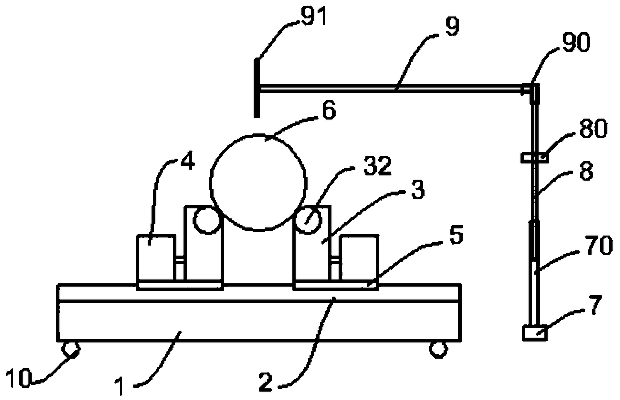
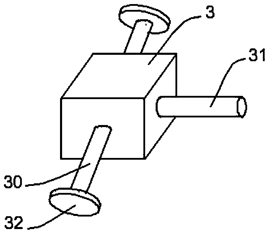
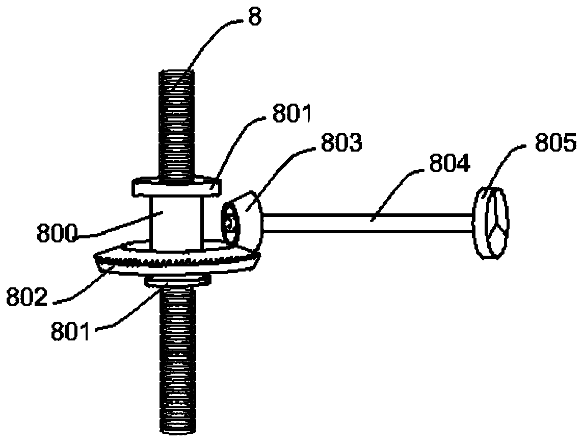
The invention discloses a plasma cutting machine with the adjustable cutting handle position. The machine comprises a base, a guide rail arranged on the base, two sets of gearboxes oppositely arranged, a support vertically provided with a first cylinder, a screw and a telescopic rod; the two side faces of the two sets of gearboxes are symmetrically provided with a telescopic shaft, each gearbox is provided with an input shaft, each input shaft is connected with an output shaft of a variable-speed motor, one gearbox and the variable-speed motor connected with the gearbox are in sliding connection to the guide rail through a sliding block, and a rotating wheel is arranged on the end side of the telescopic shaft; one end of the screw is in screw joint with the first cylinder, and a lifting device enabling the screw to ascend and descend is arranged on the screw; the telescopic rod is perpendicular to the other end of the screw through a bend, a welding handle is fixed to the free end of the telescopic rod through a clamping part, and the welding handle is located above a round pipe to be cut. According to the plasma cutting machine, a cutting handle is adjustable in position, and the cost is low.

Description

technical field [0001] The invention relates to the field of pipe cutting. More specifically, the present invention relates to a plasma cutting machine with adjustable cutting handle. Background technique [0002] At present, many pipes are cut by plasma cutting. Plasma cutting is a processing method that uses the heat of a high-temperature plasma arc to locally melt (and evaporate) the metal at the incision of the pipe, and uses the momentum of the high-speed plasma to remove the molten metal to form a cut. The plasma cutting machine has the advantages of fast cutting, small thermal deformation, small dross, low cost, etc., but the general CNC plasma cutting machine is expensive and troublesome to adjust the position of the cutting handle. Controlling the position of the cutting handle is likely to cause uneven groove formation. It can be seen that there is a need to improve the plasma cutting machine, which can cut pipes of various diameters and form uniform grooves whi...

Claims


Application Information

Patent Timeline
Patent Type & Authority Patents(China)
IPC IPC(8): B23K10/00
CPCB23K10/00
Inventor 熊斌任维茹桂军文张鹏程李钢领
Owner THE SIXTH CONSTR CO LTD OF CHINA NAT CHEM ENG
Why Eureka
Eureka Blog
Learn More