
Barrier gate applied to community entrance

A technology of gate and entrance, applied in the field of gates at the entrance of the community, can solve the problems of rigid structure, inability to realize expansion and contraction, and high transportation costs, and achieve the effects of compact structure, free retractable and strong warning effect.

Inactive Publication Date: 2017-06-13
RUIAN MIAOSHI DOOR IND
View PDF10 Cites 5 Cited by
  • Summary
  • Abstract
  • Description
  • Claims
  • Application Information

AI Technical Summary

Problems solved by technology

[0003] There are various barrier devices in the prior art, and most of the barrier devices include a barrier box main body and a barrier lever installed on the lifting arm of the barrier box for blocking. This barrier lever is It is composed of a straight rod with a fixed length. Some lengths of straight rods require large trucks to be transported, resulting in difficult transportation and high transportation costs. Although some manufacturers have also developed some splicable barrier gate products. The gate bar is spliced ​​by two to three groups of short bars, but the structure is relatively rigid. After the splicing is completed, its length is still fixed and cannot be stretched. For the community, the main function of the barrier gate during the day is to block and To manage the entry and exit of vehicles, but at night, pedestrians who enter and exit in the evening need to be released. This requires the width limit distance of the barrier bar to be shortened to allow passage for people to pass through, and the space under the barrier bar needs to prevent children from entering and exiting. Randomly interspersed and played here to prevent children from being injured, but the above problems cannot be solved in the prior art

Method used


Image

  • Barrier gate applied to community entrance
  • Barrier gate applied to community entrance

Examples


Embodiment Construction

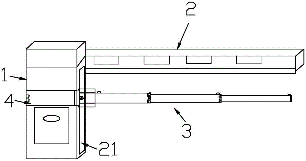
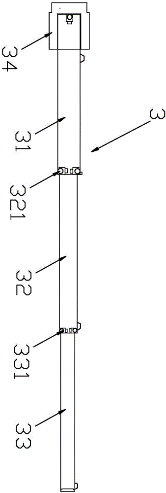
[0020] see Figure 1-Figure 2 Shown: a barrier gate applied to the entrance of a residential area, which includes a barrier gate box main body 1, on which a main gate gate lever 2 is installed, and is characterized in that: the barrier gate box main body 1 is in contact with A cavity 21 with an opening is provided on the side connected with the gate bar 2 of the main road, and a telescopic gate bar device 3 for the secondary road is arranged in the cavity 21, and the gate bar device 3 for the secondary road includes a first-time gate that is all hollow. The gate bar 31, the second gate bar 32, and the third gate bar 33, the third gate bar 33 is installed inside the second gate bar 32, the second gate bar 32 Installed inside the gate bar 31 for the first time, the sum of the lengths of the gate bar 31 for the first time, the gate bar 32 for the second time, and the gate bar 33 for the third time is equal to the length of the gate bar 2 for the main road. The inside of the firs...


PUM


Abstract

The invention relates to a barrier gate applied to a community entrance. The barrier gate comprises a barrier gate box main body, wherein a main barrier gate rod is arranged on the barrier gate box main body. The barrier gate is characterized in that a cavity with an opening is formed in one side connected with the main barrier gate rod of the barrier gate box main body, and a telescopic secondary barrier gate rod device is arranged in the cavity; the secondary barrier gate device comprises a hollow first secondary barrier gate rod, a hollow second secondary barrier gate rod and a hollow third secondary barrier gate rod; the third secondary barrier gate rod is arranged in the second secondary barrier gate rod, the second secondary barrier gate rod is arranged in the first secondary barrier gate rod, and the length sum of the first secondary barrier gate rod, the second secondary barrier gate rod and the third secondary barrier gate rod is equal to the length of the main barrier gate rod. The barrier gate disclosed by the invention has the beneficial effects that a structure is compact, the secondary barrier gate rods are flexible to collect and release, and an intercepting and alarming effect of the barrier gate is stronger.

Description

technical field [0001] The invention relates to the field of barrier gates, in particular to a barrier gate applied to the entrance of a community. Background technique [0002] Barrier gates, also known as car stoppers, are equipment specially used to manage the entrance and exit of passages that restrict motor vehicles on the road. Because of their convenience, speed, accuracy, and great reduction of human workload, they are widely used in highway toll stations , parking lots, major residential areas and corporate factories, etc. [0003] There are various barrier devices in the prior art, and most of the barrier devices include a barrier box main body and a barrier lever installed on the lifting arm of the barrier box for blocking. This barrier lever is It is composed of a straight rod with a fixed length. Some lengths of straight rods require large trucks to be transported, resulting in difficult transportation and high transportation costs. Although some manufacturers ...

Claims


Application Information

Patent Timeline
IPC IPC(8): E01F13/06
CPCE01F13/06
Inventor 缪胜光
Owner RUIAN MIAOSHI DOOR IND
Learn More