
Odor-resistant floor drain with gas-preventive barrel

A floor drain and gas-proof technology, applied in waterway systems, drainage structures, water supply devices, etc., can solve problems such as poor floor leakage and deodorization effect, and achieve the effects of smooth drainage and simple structural design.

Inactive Publication Date: 2017-06-13
翟立春
View PDF9 Cites 2 Cited by
  • Summary
  • Abstract
  • Description
  • Claims
  • Application Information

AI Technical Summary

Problems solved by technology

[0008] The purpose of the present invention is to provide an anti-odor floor drain with an air-proof cylinder, so as to alleviate the technical problem of the poor anti-odor effect of the floor drain in the prior art

Method used


Image

  • Odor-resistant floor drain with gas-preventive barrel
  • Odor-resistant floor drain with gas-preventive barrel
  • Odor-resistant floor drain with gas-preventive barrel

Examples


Embodiment 1

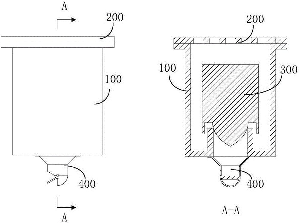
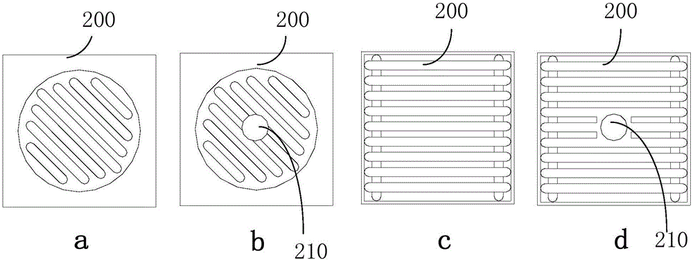
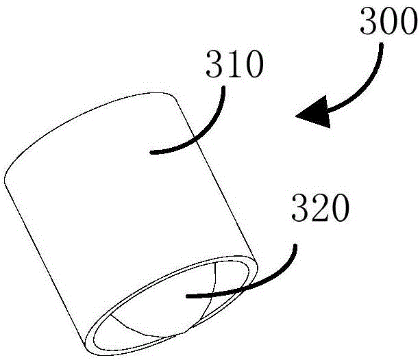
[0082] This embodiment provides an anti-odor floor drain with an air-proof cylinder, which includes a floor drain body, a floor drain cover and a float; the floor drain cover is arranged at the opening of the upper end of the floor drain body; the lower end of the floor drain body is connected to a drain pipe; the The float is arranged inside the floor drain body, the float is arranged above the drain pipe, the lower end of the float is provided with an air-proof cylinder, and the air-proof cylinder is set on the outside of the drain pipe, and the bottom of the float Cooperate with the top of the drain pipe and the inner wall of the floor drain body.

[0083] The working process of the floor drain is briefly described as follows: In the initial state, the float 300 is in contact with the water outlet 101 of the floor drain (the float 300 seals the water outlet 101 of the floor drain). The upward buoyancy of the 300 increases gradually. When the upward buoyancy of the water act...

Embodiment 3

[0110] This embodiment provides a floor drain, please refer to Figure 11 with Figure 12 ,

[0111] The floor drain includes: a floor drain body 100, a floor drain cover 200 and a float 300, wherein the floor drain cover 200 includes a cover wall and a cover top, the cover top is arranged below the cover wall, and the cover wall is detachably connected above the inside of the floor drain body 100; the floor drain body The lower end of 100 is connected with the drain pipe, the float 300 is bowl-shaped, and the float 300 is arranged above the water outlet 101 . The lower end of the float 300 is provided with an air-proof cylinder, and the air-proof cylinder is set on the outside of the drain pipe, and the bottom of the float 300 cooperates with the top of the drain pipe and the inner wall of the floor drain. When the floor drain cover 200 is in normal use ( Figure 11 ), the opening formed by the cover wall and the top of the cover faces downward, and after the floor drain c...


PUM


Abstract

The invention relates to the technical field of floor drains, in particular to an odor-resistant floor drain with a gas-preventive barrel. By the aid of the odor-resistant floor drain, the technical problem of poor odor-resistant effects of existing floor drains in the prior art can be solved. The odor-resistant floor drain comprises a floor drain, a floor drain cover and a floater. The floor drain cover is arranged at an opening in the upper end of the floor drain; the lower end of the floor drain is connected with a drain pipe; the floater is arranged inside the floor drain and is arranged on the upper side of the drain pipe, the gas-preventive barrel is arranged at the lower end of the floater and sleeves the drain pipe, and the bottom of the floater is matched with the upper side of the drain pipe and the inner wall of the floor drain. The odor-resistant floor drain has the advantages that the gas-preventive barrel is arranged at the bottom of the floor drain, can be opened when sufficient water flows through the gas-preventive barrel and can be closed when no water flows through the gas-preventive barrel or only insufficient water flows through the gas-preventive barrel, accordingly, sealing effects can be realized, and the technical problem of the poor odor-resistant effects of the existing floor drains can be solved.

Description

technical field [0001] The invention relates to the technical field of floor drains, in particular to an odor-proof floor drain with an air-proof cylinder. Background technique [0002] The floor drain is an important interface connecting the drainage pipe system and the indoor ground. As an important part of the drainage system in the house, the most basic function of the floor drain is to leak water. However, if the floor drain only has the function of leaking water, it is far from meeting the needs of people's production and life. Since the peculiar smell in the drainage pipe is easy to flow back to the bathroom through the floor drain, the backflow of the peculiar smell will seriously affect the air quality in the bathroom and the living environment of people. In daily life, some families sometimes have the occurrence of floor drain backwater, which brings a lot of troubles to people. In order to improve the odor reflux and backwater problems of floor drains, people hav...

Claims


Application Information

Patent Timeline
IPC IPC(8): E03F5/04E03F5/042E03F5/06
CPCE03F5/0407E03F5/042E03F5/06E03F2005/0416
Inventor 翟立春
Owner 翟立春
Learn More