Integrated ceiling mounting support

A technology for installing brackets and integrated ceilings, which is applied to ceilings, building components, buildings, etc., can solve the problems of complicated installation, non-adjustable, and many installation tools, and achieve the effect of simple installation

Pending Publication Date: 2017-06-13
GUANGDONG NEDFON INDOOR AIR SYST TECH
View PDF0 Cites 0 Cited by
  • Summary
  • Abstract
  • Description
  • Claims
  • Application Information

AI Technical Summary

Problems solved by technology

[0004] However, the installation structure in the prior art requires more installation tools, and the installation is complicated; and after the boom is installed, the installation position of the installation item is fixed and cannot be adjusted.

Method used


Image

  • Integrated ceiling mounting support
  • Integrated ceiling mounting support
  • Integrated ceiling mounting support

Examples


Embodiment 1

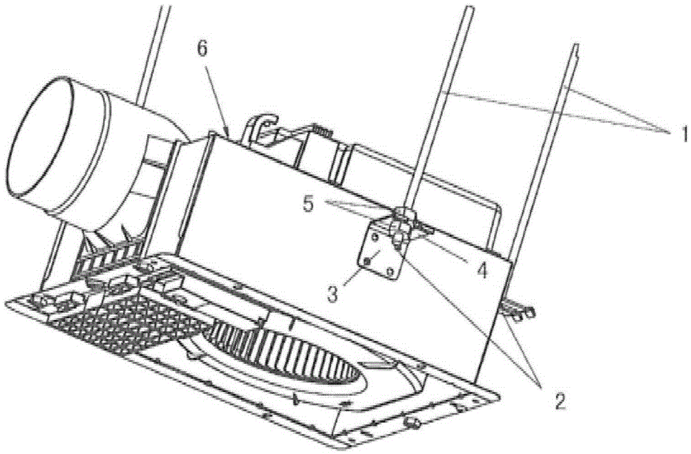
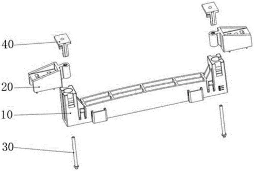
[0029] see figure 2 , which is an exploded schematic view of the overall structure of the integrated ceiling mounting bracket of the present invention. The integrated ceiling installation bracket includes a hoisting beam 10 , a hoisting support 20 , an adjusting screw 30 and a hoisting limit block 40 .

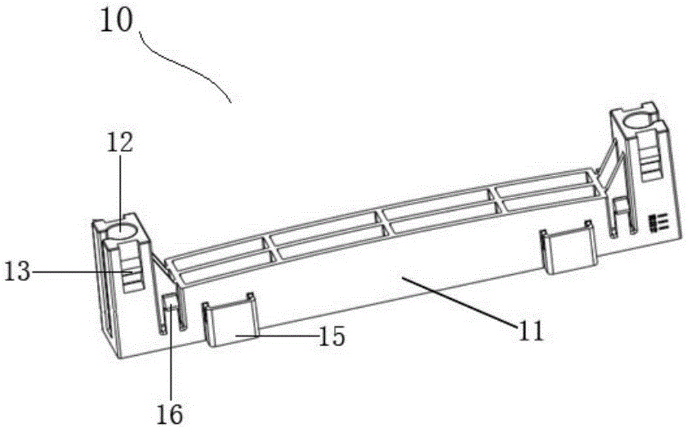
[0030] see image 3 , which is a structural schematic diagram of the suspension beam 10 . The hoisting beam 10 includes a beam 11 , a slideway 12 arranged at the end of the beam 11 , a slot 13 arranged outside the slideway 12 , a support frame 15 and a self-locking buckle 16 arranged on the side wall of the beam 11 . In this embodiment, the slideway 12 runs through the upper end surface and the lower end surface of the beam 11 in the vertical direction. The support frame 15 is mated and connected with the installation groove of the matching installation item, and the self-locking buckle 16 is matched and connected with the anti-loosening boss of the matching installation i...

Embodiment 2

[0040] see Figure 10 , which is a schematic diagram of the structure of the connected components in this embodiment. The content of this embodiment is basically the same as that of Embodiment 1, the difference is that the hoisting support 20 further includes a hollow positioning column 26 disposed below the support plate 24 . The support plate 24 is provided with a positioning hole corresponding to the hollow positioning post 26 .

[0041] see Figure 11 , which is a schematic diagram of the installation of the integrated ceiling installation bracket and the keel in this embodiment. When the width of the keel A exceeds the support range of the two elastic buckles 25 in the lifting support 20, the two buckles 25 are broken off, and the self-tapping screw B is used to connect the positioning hole and the positioning hole of the lifting support 20 The column 26 passes through, and directly locks the hoisting support 20 and the keel A with screws. Through this structural arra...


PUM


Abstract

An integrated ceiling mounting support comprises a hoisting cross beam, hoisting supporting pieces, adjusting screws and hoisting limiting blocks. The hoisting cross beam comprises a cross beam body, sliding ways arranged at the ends of the cross beam body, clamping grooves formed in the outer sides of the sliding ways and round holes formed in the bottoms of the sliding ways. Each hoisting supporting piece comprises a supporting plate, a sliding block arranged at one end of the supporting plate and matched with the corresponding sliding way and two elastic buckles arranged below the supporting plate. The hoisting supporting pieces are inserted into the sliding ways through the sliding blocks. A center hole is formed in the center of each sliding block, and an embedded nut is arranged in each center hole. The adjusting screws penetrate through the round holes and the center holes to be in threaded connection with the embedded nuts. The hoisting limiting blocks are arranged on the upper end faces of the sliding ways and each comprises a cover plate and two hook claws vertically arranged at the two opposite ends of the cover plate and adaptive to the clamping grooves, and the two hook claws of each hoisting limiting block are buckled in the corresponding clamping grooves. The integrated ceiling mounting support is simple and convenient to mount and can adapt to mounting keels in different size ranges.

Description

technical field [0001] The invention relates to a mounting bracket, in particular to a mounting bracket for an integrated suspended ceiling. Background technique [0002] The integrated ceiling is also called the integral ceiling and the integral ceiling. The ceiling module and the electrical module are made into standard-sized combinable modules, which are integrated together during installation. The integrated ceiling is divided into gusset module, heating module, lighting module and ventilation module. Integrated ceilings are generally used in kitchens, bathrooms and balconies. With the continuous development of integrated ceiling technology, at this stage, they have developed into customized ceilings for the whole room, such as living room, bedroom, study room, restaurant, and commercial decoration lighting fields. [0003] When installing the integrated suspended ceiling, it is necessary to fix the installation items to the keel on the back of the ceiling through the i...

Claims


Application Information

Patent Timeline
IPC IPC(8): E04B9/00E04B9/06E04B9/22
CPCE04B9/003E04B9/005E04B9/006E04B9/225
Inventor 谭坚裘李清泉解博超
Owner GUANGDONG NEDFON INDOOR AIR SYST TECH
Why Eureka
Try Eureka