Bilaterally reversible push-pull transmission mechanism

A transmission mechanism, left and right technology, applied in building structure, door/window accessories, handle connection, etc., can solve problems such as unfavorable standardized management, high operating costs, adverse effects of maintenance, etc., to reduce production cycle and enterprise operating costs. , the operation is simple and fast, the effect of wide practical value

Inactive Publication Date: 2017-06-13
BEIJING HUOHE TECH
View PDF6 Cites 7 Cited by
  • Summary
  • Abstract
  • Description
  • Claims
  • Application Information

AI Technical Summary

Problems solved by technology

However, none of the existing push-pull smart locks on the market can change the direction. Therefore, it is necessary to confirm the opening direction of the door before production, and then order the corresponding locks according to the specific installation direction. Not only the production cycle is long, the operating cost is high, and it is impossible Realize the unified production and distribution of locks, which is not conducive to the standardized management of market operations
In order to save the production cycle, some merchants will mass-produce locks in the same direction, and then change the direction by disassembling the parts and reassembling them during specific installation. to adversely affect

Method used


Image

  • Bilaterally reversible push-pull transmission mechanism
  • Bilaterally reversible push-pull transmission mechanism
  • Bilaterally reversible push-pull transmission mechanism

Examples


Embodiment Construction

[0023] The present invention will be further described in detail below in conjunction with the accompanying drawings and specific embodiments.

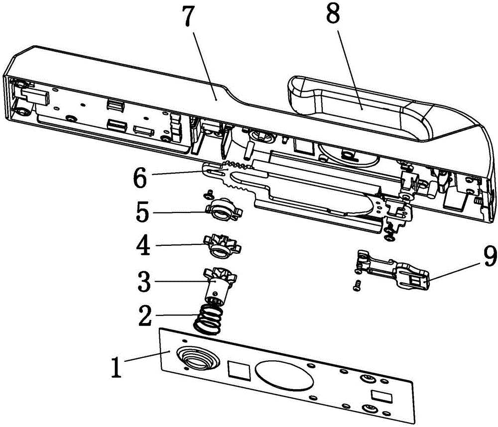
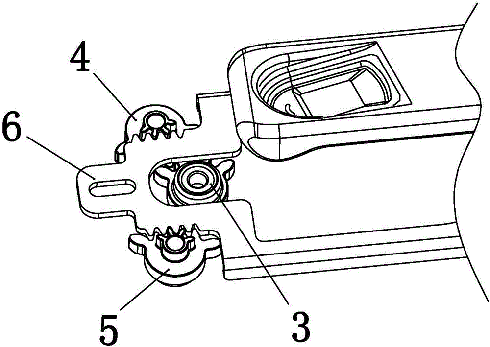
[0024] like Figure 1~4 As shown, the present invention includes a panel 7, which also includes a push-pull handle 8, a reversing gear 3, and a bottom cover 1; Accommodating space; the push-pull transmission part 9, the transmission rack 6, the reversing gear 3, the first transmission gear 4, the second transmission gear 5, and the reversing pressure spring 2 are all arranged in the accommodation space surrounded by the panel 7 and the bottom cover 1 middle.

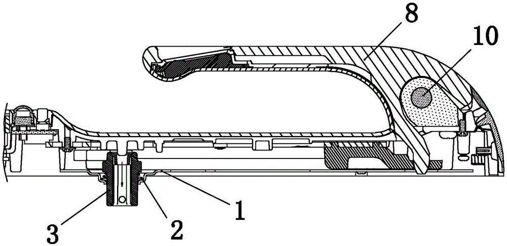
[0025] The upper right side of the panel 7 is provided with a push-pull handle 8, and the connection between the push-pull handle 8 and the panel 7 is provided with a push-pull shaft 10, and the push-pull handle 8 turns up and down around the push-pull shaft 10 to realize unlocking or closing;

[0026] The lower end of the right side of the push-pull handle 8 passes through th...


PUM


Abstract

The invention discloses a bilaterally reversible push-pull transmission mechanism which comprises a panel, a push-pull handle, a reversing gear and a bottom cover plate. The push-pull handle is arranged at the upper end of the right side of the panel and drives a push-pull transmission part to bilaterally move through a columnar projection, the left side of the push-pull transmission part is fixedly connected with a transmission rack, the reversing gear is arranged in a U-shaped opening in the left side of the transmission rack, the front end and the rear end of the reversing gear are engaged with one of a first transmission gear and a second transmission gear, a long column at the lower end of the reversing gear is inserted into a reversing pressure spring and then penetrates the bottom cover plate at the lower end of the panel, and the reversing gear is pulled downwards, rotates by 180 degrees and then is loosened, so that reversing can be realized. A push-pull intelligent lock can be bilaterally reversed, the push-pull transmission mechanism has the advantages of simplicity, convenience and rapidness in operation, standardized unified production and management of locks can be realized, so that production cycle is greatly shortened, the operation cost of enterprises is greatly reduced, and the push-pull transmission mechanism has a wide practical value.

Description

technical field [0001] The invention relates to a transmission mechanism, in particular to a push-pull transmission mechanism capable of reversing left and right. Background technique [0002] With people's exploration and pursuit of high-end smart products, push-pull smart lock applications are born. Smart lock refers to a lock that is more intelligent in terms of user identification, security, and management, which is different from traditional mechanical locks. It generally consists of a push-pull wrench, a touch screen, and a fingerprint reader. It can be opened in two ways, and has built-in camera, voice intercom and other functions. The push-pull smart lock solves the problem of some users forgetting to bring their keys, and also makes home life more classy and fashionable, becoming the key to the growth of the smart home market in the future. However, none of the existing push-pull smart locks on the market can change the direction. Therefore, it is necessary to con...

Claims


Application Information

Patent Timeline
Patent Type & Authority Applications(China)
IPC IPC(8): E05B63/04E05B3/00E05B15/00
CPCE05B3/00E05B15/00E05B63/04
Inventor 段方华钱俊郭金保
Owner BEIJING HUOHE TECH
Why Eureka
Try Eureka