Rotary projection lamp for construction site

A construction site and projection lamp technology, applied in the field of projection lamps, can solve the problems of cumbersome operation of projection lamps free rotation, fixed lighting angle of projection lamps, and inability to realize all-round lighting, etc., to improve convenience, reduce labor costs, and structure simple effect

Active Publication Date: 2017-06-13
连云港明昊电子有限公司
View PDF5 Cites 5 Cited by
  • Summary
  • Abstract
  • Description
  • Claims
  • Application Information

AI Technical Summary

Problems solved by technology

When solving multi-directional lighting in different time periods, it is usually solved by reinstalling the searchlight orientation or increasing the number of searchlights, which is very inconvenient in actual use and requires a lot of investment, or directly fix related facilities such as projection lights and switch boxes at will. A certain fixed point on the site, and the operation of the free rotation of the projection lamp is extremely cumbersome, which affects the efficiency of on-site construction; moreover, the projection lamp in the prior art has a fixed lighting angle and has a large dead angle, which cannot realize omnidirectional lighting, and the work efficiency is low. Difference

Method used


Image

  • Rotary projection lamp for construction site
  • Rotary projection lamp for construction site
  • Rotary projection lamp for construction site

Examples


Embodiment Construction

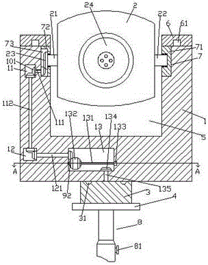
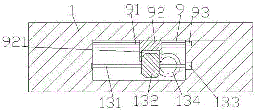
[0022] Such as Figure 1-Figure 5 As shown, a construction site rotary projection lamp of the present invention includes a mounting frame body 1 with a groove 5 on the inner top and a mounting seat 3 that is rotatably connected to the bottom of the mounting frame body 1 . A projection lamp assembly 2 is provided, a searchlight head 24 is provided on the front end of the projection lamp assembly 2, a first rotating shaft 21 and a second rotating shaft 22 are respectively provided on the left and right sides of the projection lamp assembly 2, and the first rotating shaft 21 is left The side end is rotatably connected with a first slider 72, and an opening groove 73 is arranged in the first slider 72, and a third conical wheel 23 fixedly connected with the first rotating shaft 21 is arranged in the opening groove 73. The right end of the second rotating shaft 22 is rotatably connected with a second slider 71, and the tops of the inner walls on the left and right sides of the groo...


PUM


Abstract

The invention discloses a rotary projection lamp for a construction site. The rotary projection lamp comprises a mounting rack with a groove formed in the inner top and a mounting base in rotating fit connection with the bottom of the mounting rack, wherein a projection lamp module is arranged in the groove, a searchlight holder is arranged on the front end surface of the projection lamp module, a first rotating shaft and a second rotating shaft are arranged on left and right sides of the projection lamp module respectively, the tail end of the left side of the first rotating shaft is in rotating fit connection with a first slider, an open slot is formed in the first slider, a third conical wheel fixedly connected with the first rotating shaft is arranged in the open slot, the tail end of the right side of the second rotating shaft is in rotating fit connection with a second slider, mounting grooves are symmetrically formed in tops of inner walls of left and right sides of the groove, a first cavity is formed in the mounting rack and on one side, far away from the groove, of the mounting groove on the left side, a second cavity is formed in the mounting rack below the first cavity, a third cavity is formed in the mounting rack and on the right side of the second cavity, a spline driving rod extending bilaterally is arranged in the third cavity, and the right side end of the spline driving rod is in power connection with a first motor.

Description

technical field [0001] The invention relates to the technical field of projection lamps, in particular to a rotating projection lamp for a construction site. Background technique [0002] Projector lights are commonly used lighting equipment on construction sites, and their proper arrangement directly affects the construction at night and in dark environments. At present, the traditional way is to use fixed searchlights to solve lighting problems. Ways are adopted: frame body fixing, rod body fixing, fixing on the ground by means of structure fixing, etc. When solving multi-directional lighting in different time periods, it is usually solved by reinstalling the searchlight orientation or increasing the number of searchlights, which is very inconvenient in actual use and requires a lot of investment, or directly fix related facilities such as projection lights and switch boxes at will. A certain fixed point on the site, and the operation of the free rotation of the projectio...

Claims


Application Information

Patent Timeline
Patent Type & Authority Applications(China)
IPC IPC(8): F21S8/00F21V14/02F21V17/16F21V21/30
CPCF21S8/00F21V14/02F21V17/164F21V21/30
Inventor 范翠贞
Owner 连云港明昊电子有限公司
Why Eureka
Try Eureka