Method for converting and displaying waveform display data of digital fluorescent oscilloscope

A waveform display and digital phosphor technology, applied in the display field of digital phosphor oscilloscopes, can solve the problems of loss of display information, users unable to observe signals, loss and other problems

Active Publication Date: 2017-06-13
SOUTHEAST UNIV
View PDF4 Cites 4 Cited by
  • Summary
  • Abstract
  • Description
  • Claims
  • Application Information

AI Technical Summary

Problems solved by technology

The commonly used linear compression conversion adopts the same compression ratio for waveform points with high frequency of occurrence and waveform points with low frequency of occurrence. After compression, some display information of waveform points with low frequency of occurrence will often be lost, especially when the waveform When the frequency of occurrence of each point in the value differs greatly, those waveform points that only appear a few times will be lost due to compression, so that users cannot observe these occasional signals

Method used


Image

  • Method for converting and displaying waveform display data of digital fluorescent oscilloscope
  • Method for converting and displaying waveform display data of digital fluorescent oscilloscope
  • Method for converting and displaying waveform display data of digital fluorescent oscilloscope

Examples


Embodiment Construction

[0054] Below in conjunction with accompanying drawing and specific embodiment, further illustrate the present invention, should be understood that these examples are only for illustrating the present invention and are not intended to limit the scope of the present invention, after having read the present invention, those skilled in the art will understand various aspects of the present invention All modifications of the valence form fall within the scope defined by the appended claims of the present application.

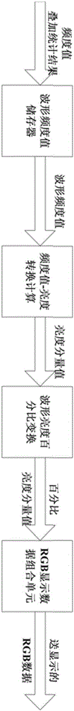
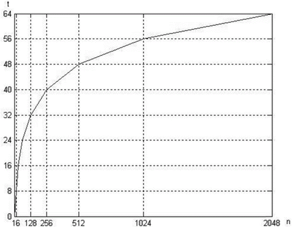
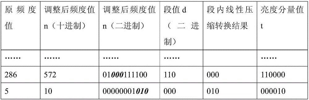
[0055] A digital phosphor oscilloscope waveform display data conversion calculation method, such as figure 1 As shown, the statistical waveform frequency value of each point waveform is converted into a display brightness component value by a method that is convenient for hardware implementation, and the display brightness component value can be changed according to the display brightness set by the user and converted to RGB format Display Data. The method of conver...


PUM


Abstract

The invention discloses a method for converting and displaying waveform display data of a digital fluorescent oscilloscope. The frequency values of the waveforms of each point under the statistics are converted to display brightness component values by a method that is easy to implement by hardware and the display brightness component values can be changed and converted according to the display brightness set by the user to acquire the display data in the RGB format. When a waveform frequency value is converted to a display luminance component value, firstly, the frequency value interval of the waveform is segmented according to the approximate logarithmic relation, and the linear frequency compression method is adopted to convert the frequency value to the luminance component value in each section, thus, when the high-frequency value is converted, the compression ratio is large, and when the low-frequency value is converted, the compression ratio is smaller, so that the waveform points with high frequency and low frequency waveform points can be effectively displayed in the signals under test, and also easy to realize by hardware circuit; meanwhile, the original waveform information can be completely preserved.

Description

technical field [0001] The invention relates to a digital phosphor oscilloscope waveform display method, which belongs to the technical field of digital phosphor oscilloscope display. Background technique [0002] In recent years, the measurement of dynamic and complex signals has challenged engineers and technicians. The first generation of analog real-time oscilloscopes (ART) and the second generation of digital storage oscilloscopes (DSO) seem helpless. So the third generation of oscilloscope - digital phosphor oscilloscope (DPO) came into being. Digital phosphor oscilloscopes use dedicated hardware circuits for real-time digital phosphor processing of waveform acquisition, making the capture update rate of waveforms as high as hundreds of thousands of frames per second or even millions of frames per second, which is much higher than the most advanced DSO. Therefore, it can capture image Occasional signals such as glitches and short pulses; at the same time, digital pho...

Claims


Application Information

Patent Timeline
Patent Type & Authority Applications(China)
IPC IPC(8): G01R13/02
Inventor 高礼忠
Owner SOUTHEAST UNIV
Why Eureka
Try Eureka