
Method of realizing wave-shape fluorescent display effect by multiple-channel digital oscilloscope

A technology of digital oscilloscope and display effect, applied in the direction of digital variable display, etc., can solve the problem of analog oscilloscope lacking digital storage oscilloscope storage and processing function trigger function, etc., and achieve the effect of being beneficial to waveform observation and convenient for waveform observation.

Inactive Publication Date: 2010-09-15
SOUTHEAST UNIV
View PDF0 Cites 1 Cited by
  • Summary
  • Abstract
  • Description
  • Claims
  • Application Information

AI Technical Summary

Problems solved by technology

However, analog oscilloscopes lack the storage and processing functions and advanced trigger functions that digital storage oscilloscopes have.

Method used


Image

  • Method of realizing wave-shape fluorescent display effect by multiple-channel digital oscilloscope
  • Method of realizing wave-shape fluorescent display effect by multiple-channel digital oscilloscope
  • Method of realizing wave-shape fluorescent display effect by multiple-channel digital oscilloscope

Examples


Embodiment Construction

[0044] The present invention will be further described below in conjunction with the accompanying drawings.

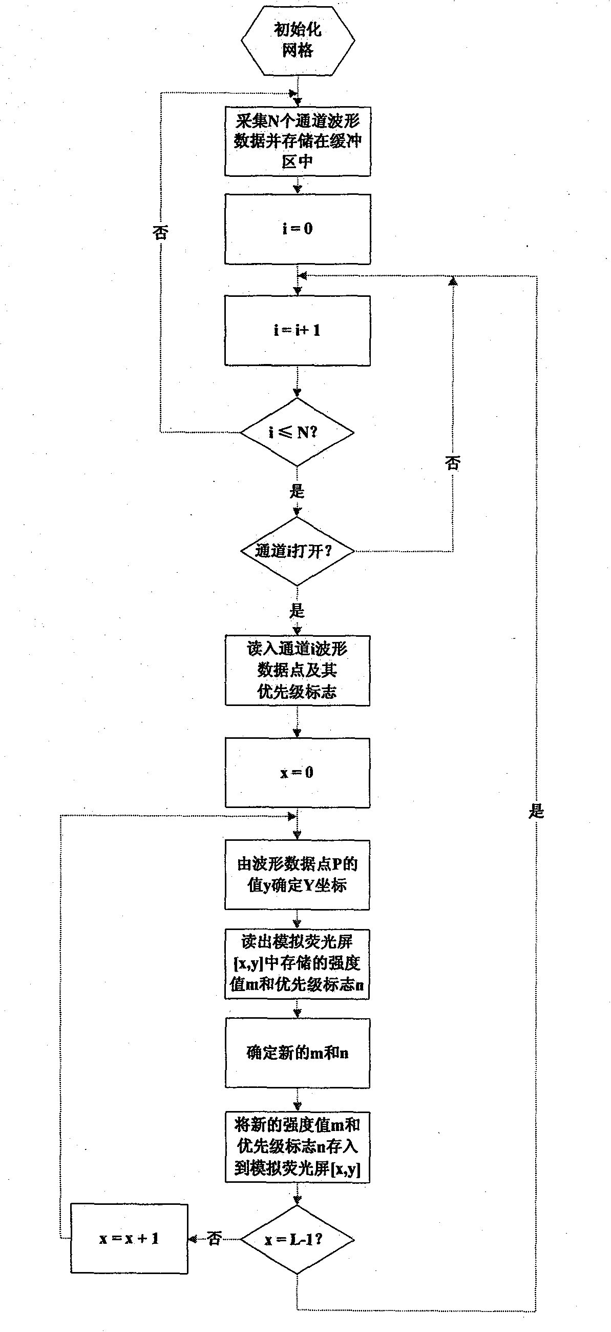
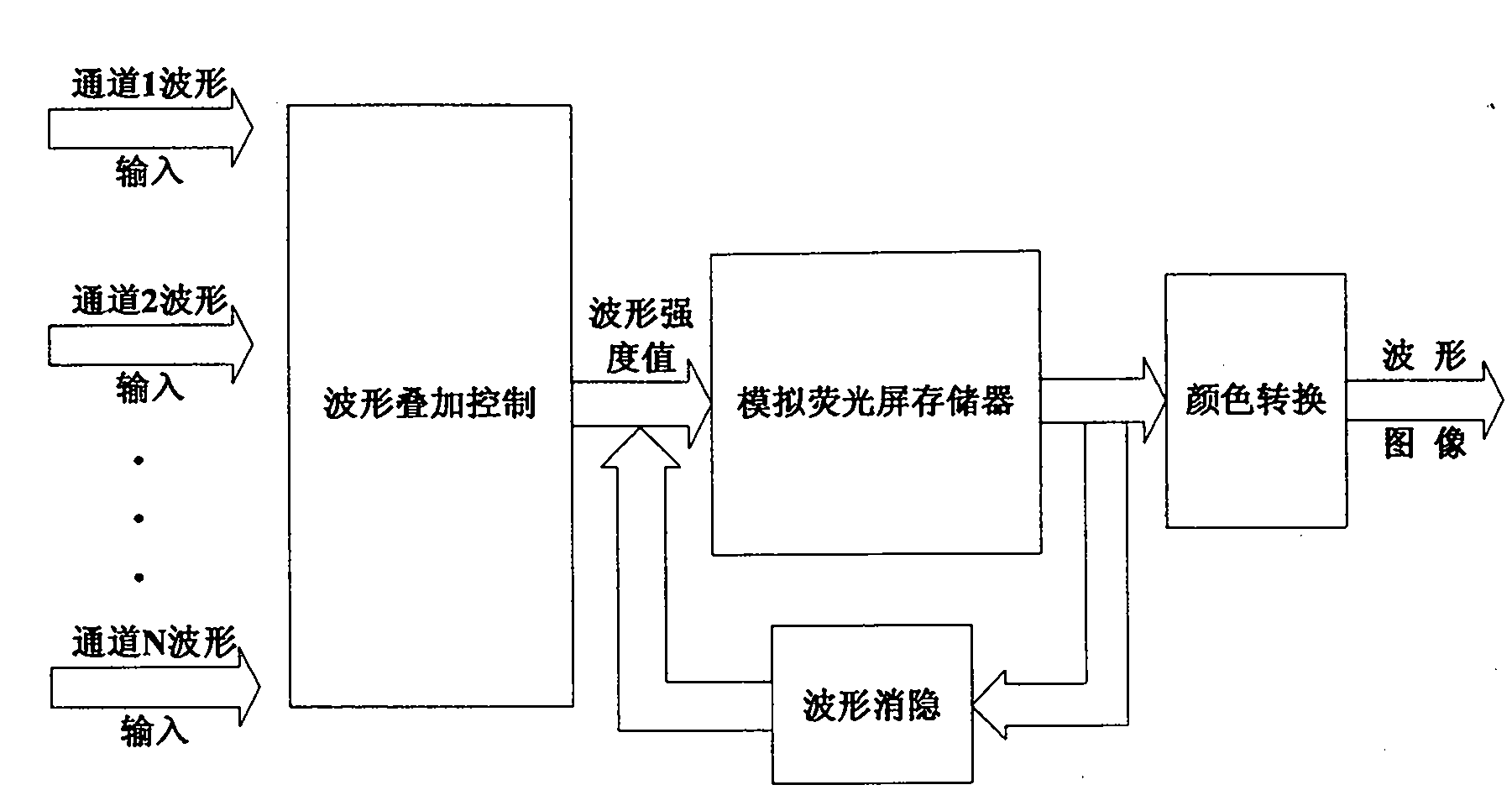
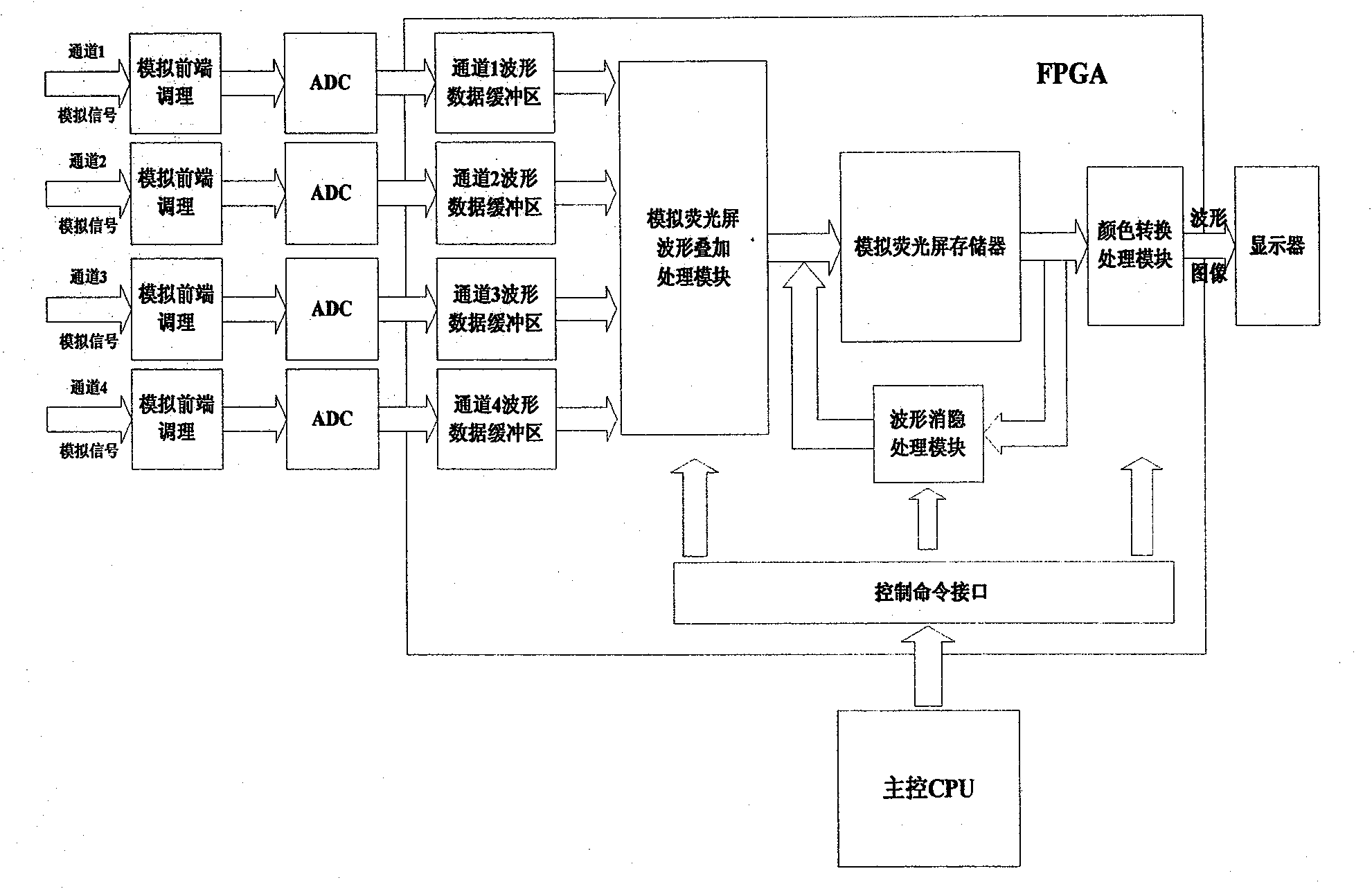
[0045] see figure 1, image 3 , the multi-channel digital oscilloscope of the present invention realizes the method for waveform fluorescent display effect comprising the following steps:

[0046] 1) Initialize the memory of the simulated fluorescent screen, and fill in the grid information;

[0047] 2) Set the intensity step value a, the grid brightness value b and the waveform blanking percentage c;

[0048] 3) Collect and store the waveform signals of N channels;

[0049] 4) Read out the waveform data points of the stored N channels in sequence, perform superposition processing according to the priority of the channels, and then store them in the memory of the analog fluorescent screen;

[0050] 5) Regularly convert the waveform intensity value stored in the memory of the analog fluorescent screen into a color value and perform blanking processing.

[0051] Whe...


PUM


Abstract

The invention provides a method for realizing wave-shape fluorescent display effect by a multiple-channel digital oscilloscope, which can be realized by a programmable logic device. The programmable logic device comprises a wave-shape data buffer area, an analogue fluorescent screen memory, a wave-shape superposition treatment module, a wave-shape blanking treatment module and a color conversion treatment module. The length and the height of the analogue fluorescent screen memory are respectively L and W. Each memorizing unit of the analogue fluorescent screen memory consists of strength value W and priority signal n, wherein the range of the strength value W is greater than or equal to 0 and smaller than or equal to W; M is decided by the level width of the strength value in the analoguefluorescent screen memory and is the maximum value represented by the level width of the strength value; the priority sequence is sequentially from a network grid, a newly opened channel, a channel 1, a channel 2 to a channel I, and the like until a channel N. The method integrally saves the luminance level information displayed by multiple channels and achieves the fluorescent display effect of analogue oscilloscopes.

Description

technical field [0001] The invention relates to the technical field of waveform display of a digital oscilloscope, in particular to a waveform display method of a multi-channel digital oscilloscope. Background technique [0002] In recent years, the measurement of dynamic and complex signals has challenged engineers and technicians. The first generation of analog real-time oscilloscopes (ART) and the second generation of digital storage oscilloscopes (DSO) seem helpless. Analog oscilloscopes have a brightness display function that digital oscilloscopes lack, that is, through different brightness, the frequency of occurrence of different parts of the signal is reflected. However, analog oscilloscopes lack the storage and processing functions and advanced trigger functions that digital storage oscilloscopes have. Therefore, neither of the above two oscilloscopes can be relied on alone to meet the measurement needs of dynamic and complex signals. It is necessary to combine th...

Claims


Application Information

Patent Timeline
Patent Type & Authority Patents(China)
IPC IPC(8): G01R13/02
Inventor 高礼忠贺丙杰罗张孔凡洪吴帆扬
Owner SOUTHEAST UNIV
Learn More