Check patentability & draft patents in minutes with Patsnap Eureka AI!

Multi-energy flow system multi-target optimal power flow model and solving method thereof

A multi-objective optimal power flow model technology, applied in the fields of instruments, data processing applications, forecasting, etc., can solve problems such as establishment of multi-objective optimal power flow model and research on its solution method

Inactive Publication Date: 2017-06-13
CHANGSHA UNIVERSITY OF SCIENCE AND TECHNOLOGY
View PDF0 Cites 6 Cited by
  • Summary
  • Abstract
  • Description
  • Claims
  • Application Information

AI Technical Summary

Problems solved by technology

Although these have achieved certain results in the modeling and solving of multi-energy flow networks, there has not been research on the establishment of multi-objective optimal power flow models for multi-energy flow systems and their solution methods.

Method used


Image

  • Multi-energy flow system multi-target optimal power flow model and solving method thereof
  • Multi-energy flow system multi-target optimal power flow model and solving method thereof
  • Multi-energy flow system multi-target optimal power flow model and solving method thereof

Examples


Embodiment Construction

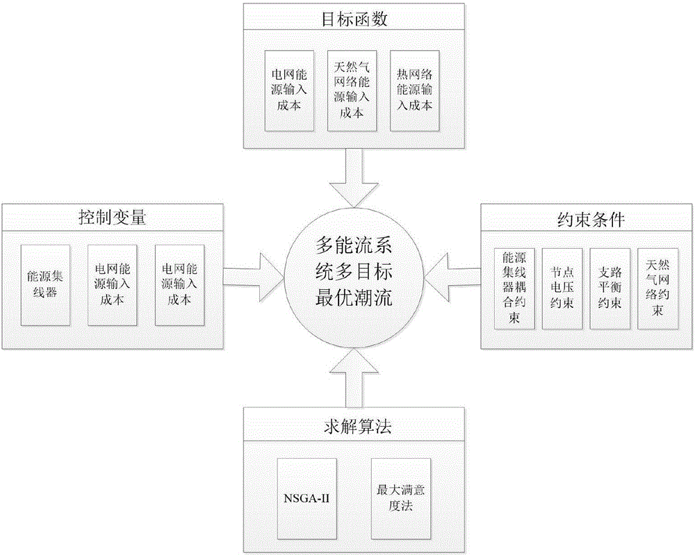
[0010] The present invention comprises the following steps:

[0011] Step 1: Propose a multi-objective optimal power flow model based on multi-energy flow system

[0012] (1) Decision variable vector

[0013]

[0014] where s i and v i are the virtual factor and dispatch factor in the energy hub, P ei ,P gi ,P hi are the energy input in the energy hub, are the active output and node voltage of the power network units, respectively, R Nc ,p Nn are the compression ratio and node pressure of the compressor in the natural gas network, respectively.

[0015] In this example, the multi-energy coupling system has 11 energy hubs, the power network is modeled on the IEEE 5-machine 14-node standard system, and the natural gas network is modeled on 3-compressor 22 nodes, so there are 99 decision variables.

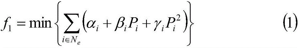
[0016] (2) Objective function

[0017]

[0018]

[0019]

[0020] (3) Constraints

[0021] 1) Equality constraints

[0022] 1. Energy Hub Coupling Constraint...


PUM


Abstract

The invention discloses a multi-energy flow system multi-target optimal power flow model and a solving method thereof, and relates to the field of multi-energy flow system operation control. The method comprises the following steps of: establishing the multi-energy flow system multi-target optimal power flow model through considering constraint conditions such as a virtual factor, a scheduling factor and input energy of an energy concentrator, active power output and node voltage of a power network unit, and a compressor compression ratio and node pressure intensity of a natural gas network by minimizing a power network input energy cost, a natural gas network input energy cost and a thermal network input energy cost; and solving a multi-target optimal power flow model on the basis of NSGA-II and maximum satisfiability method mixed algorithm, so as to obtain a Pareto solution set and an optimal compromise solution of a multi-energy flow system multi-target optimal power flow. The multi-energy flow system multi-target optimal power flow model and the solving method are suitable for the energy interconnection development trend, and can decrease the operation cost while the energy utilization efficiency of multi-energy flow systems is improved.

Description

technical field [0001] The invention relates to a multi-objective optimal power flow model of a multi-energy flow system and a solution method thereof, belonging to the field of operation control of a multi-energy flow system. Background technique [0002] With the increasingly prominent energy and environmental issues, the Energy Internet is a frontier and hot spot in the field of energy research. Building a multi-energy flow system can help improve the energy efficiency of a multi-energy flow system and reduce energy input costs. The continuous development of multi-energy flow coupling has made it difficult to directly apply the traditional single-energy flow system method. In order to ensure the efficient operation of multi-energy flow systems, it is urgent to develop multi-energy flow-oriented energy management. Based on this, a multi-objective optimal power flow model and its solution method for multi-energy flow systems are proposed, which has certain significance for ...

Claims


Application Information

Patent Timeline
Patent Type & Authority Applications(China)
IPC IPC(8): G06Q10/04G06Q50/06
CPCG06Q10/04G06Q50/06
Inventor 马瑞秦佳倩颜宏文
Owner CHANGSHA UNIVERSITY OF SCIENCE AND TECHNOLOGY
Features
  • R&D
  • Intellectual Property
  • Life Sciences
  • Materials
  • Tech Scout
  • Unparalleled Data Quality
  • Higher Quality Content
  • 60% Fewer Hallucinations
Learn More