

No-fly zone unmanned aerial vehicle early-warning method
A technology for unmanned aerial vehicles and no-fly zones, applied in aircraft traffic control, radio wave measurement systems, satellite radio beacon positioning systems, etc.
Active Publication Date: 2017-06-13
UNIV OF ELECTRONICS SCI & TECH OF CHINA
View PDF5 Cites 38 Cited by
- Summary
- Abstract
- Description
- Claims
- Application Information
AI Technical Summary
Problems solved by technology
However, compared with the maturity of drone technology, the supervision technology of drones is relatively backward, especially the supervision of drones around no-fly zones such as airports is even more lacking.
Method used
View moreImage
Smart ImageViewing Examples

Examples
Embodiment Construction
[0069] The technical solution of the present invention has been described in detail in the part of the summary of the invention, and will not be repeated here.
Login to View More PUM
 Abstract
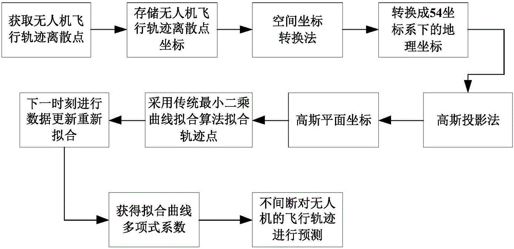
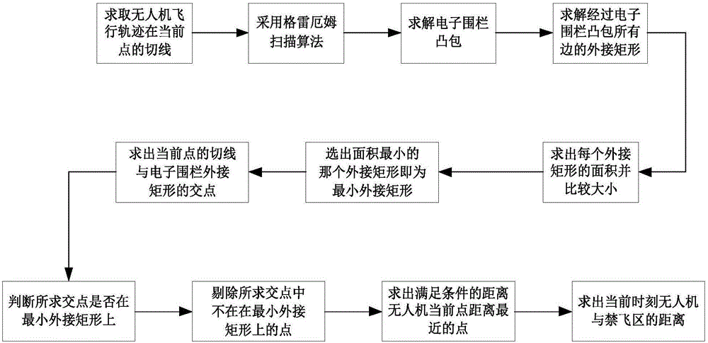
The invention belongs to the technical field of unmanned aerial vehicle regulation and particularly relates to a no-fly zone unmanned aerial vehicle early-warning method. The method comprises the steps of firstly, acquiring a certain number of longitude and latitude coordinate points of an unmanned aerial vehicle flying in a current time period, through coordinate transformation, transforming the points to corresponding plane coordinate points in a rectangular plane coordinate system, then, using an improved least square method to conduct curve fitting on corresponding discrete plane coordinate points, fitting a flight path of the unmanned aerial vehicle in this period, finally, obtaining a tangent line of a current point of a fitting curve, and judging whether or not the unmanned aerial vehicle can enter a no-fly zone by judging whether or not the tangent line is intersected with an electronic fence for describing the no-fly zone. If yes, real-time distance between the current point and the no-fly zone is obtained and an alarm is given in time, and if not, prediction for the next moment is carried out. The no-fly zone unmanned aerial vehicle early-warning method has a wide application prospect in the field of civilian unmanned aerial vehicle regulation.
Description
technical field [0001] The invention belongs to the technical field of unmanned aerial vehicle supervision, and in particular relates to an early warning method for unmanned aerial vehicles in a no-fly zone. Background technique [0002] With the continuous development of drone technology, more and more small civilian drones are used in our daily life. However, compared with the maturing of drone technology, the supervision technology of drones is relatively backward, especially the supervision of drones around no-fly zones such as airports is even more lacking. In order to ensure traffic safety in low airspace and prevent drones around the no-fly zone from intruding into the area, causing unnecessary safety accidents, it is necessary to carry out timely early warning and supervision of drones around the no-fly zone. Contents of the invention [0003] The purpose of this invention is to propose a kind of no-fly zone UAV early warning method. [0004] Technical scheme of ...
Claims
Login to View More Application Information
Patent Timeline
 IPC IPC(8): G08G5/00G01S19/42
Inventor闫斌叶润石凯
OwnerUNIV OF ELECTRONICS SCI & TECH OF CHINA