Picture display unit, device and method
A technology for displaying devices and screens, which is applied in the field of screen display devices and screen display units, and can solve the problems of limited number of screens, limited power supply of electronic storage and display screens, virus loss, etc.
- Summary
- Abstract
- Description
- Claims
- Application Information
AI Technical Summary
Problems solved by technology
Method used
Image
Examples
Embodiment 1
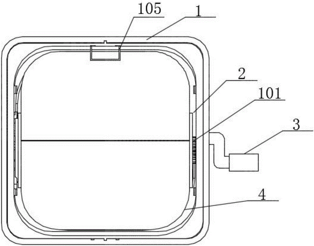
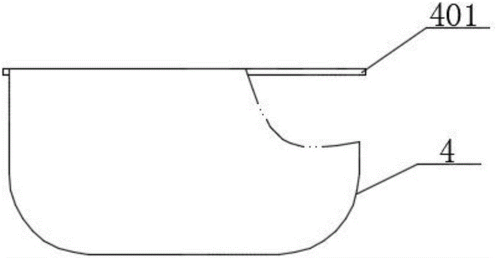
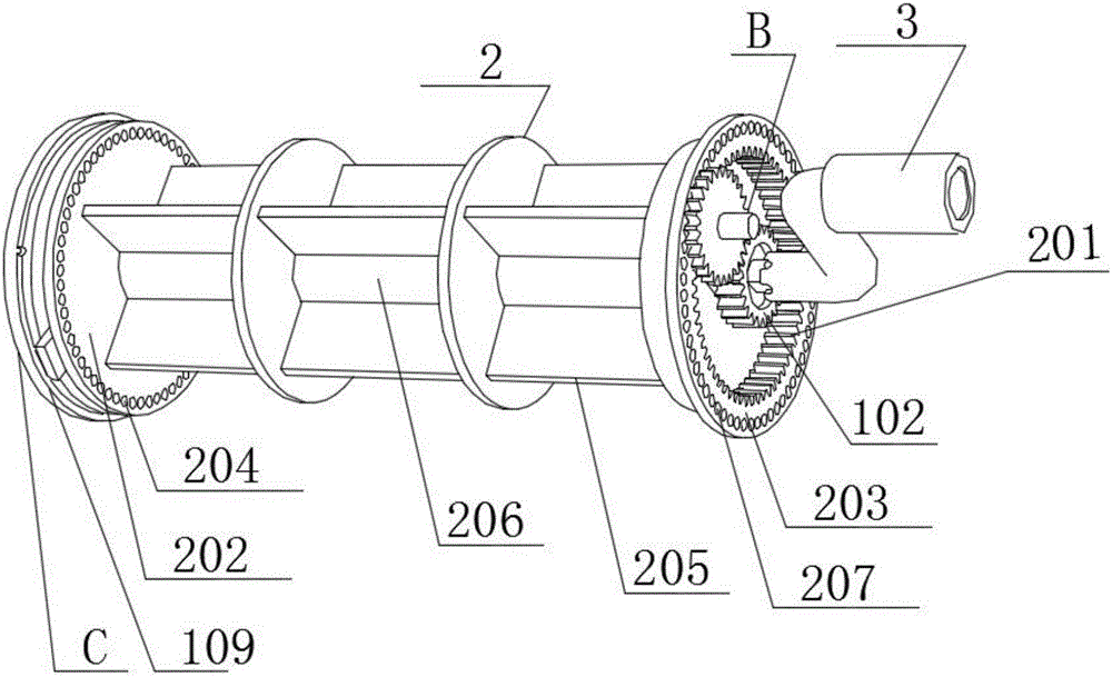
[0047] see figure 1 , figure 2 , image 3 As shown, a screen display unit provided in this embodiment includes a device box 1 with a display window; the rotating cylinder 2 is erected in the device box through a gear shaft 101, and the gear shaft 101 is passed through the On the device box 1, the rotating cylinder 2 is driven to rotate by the driving device 3; a plurality of pictures 4 are connected to the rotating cylinder through a connecting mechanism A, and the inner edge of each said picture 4 is distributed along the circumferential direction of the rotating cylinder; The rotating cylinder includes a support frame 205 with a wearing tube 206 in the middle and a first mounting plate 203 and a second mounting plate 202 arranged at both ends of the support frame. The end surface of the first mounting plate is provided with first internal teeth Ring 201, the first internal ring gear is connected to the driving device 3 through a gear transmission mechanism B; a plectrum 1...
Embodiment 2
[0055] The screen display unit in this embodiment is an improvement on the basis of Embodiment 1. The technical content disclosed in Embodiment 1 will not be described repeatedly, and the content disclosed in Embodiment 1 also belongs to the content disclosed in this embodiment.
[0056] see Figure 7 , Figure 8 As shown, the gear transmission mechanism F in this embodiment includes a first gear 901 arranged on the gear shaft and a concentric gear 902 connecting the first gear 901 and the first ring gear, the concentric The middle part of the gear is provided with a concentric gear shaft 903 , the concentric gear shaft is mounted on the gear shaft through a fixing plate 904 , and the concentric gear shaft is connected 908 with the driving device.
[0057] The screen display unit provided by the present invention adopts the gear transmission mechanism including the first gear arranged on the gear shaft and the concentric gear connecting the first gear and the first ring gear,...
Embodiment 3
[0065] see Figure 10 , Figure 11 , Figure 12 , Figure 14 As shown, a picture display device provided in this embodiment includes a drive device 6 and a plurality of primary picture display units 601 arranged side by side; each of the primary picture display units includes a gear shaft 602 and a At least one device box on the gear shaft, the device box is provided with a display window; each of the gear shafts is connected to the drive device 6; each of the device boxes is equipped with a rotating cylinder 603; each of the rotating cylinders is connected with a plurality of pictures 604 through the connecting mechanism, and the inner edge of each of the pictures is distributed along the circumferential direction of the rotating cylinder; each of the rotating cylinders includes a middle part with a wearing cylinder The support frame 605 and the first mounting plate 606 and the second mounting plate 607 arranged at both ends of the support frame, the end face of the first ...
PUM
 Abstract
Description
Claims
Application Information
 - R&D
- Intellectual Property
- Life Sciences
- Materials
- Tech Scout
- Unparalleled Data Quality
- Higher Quality Content
- 60% Fewer Hallucinations
Browse by: Latest US Patents, China's latest patents, Technical Efficacy Thesaurus, Application Domain, Technology Topic, Popular Technical Reports.
© 2025 PatSnap. All rights reserved.Legal|Privacy policy|Modern Slavery Act Transparency Statement|Sitemap|About US| Contact US: help@patsnap.com


