Novel electric shock prevention power supply device

A technology of power supply device and anti-electric shock, applied in the direction of coupling device, parts and circuit of connection device, etc., can solve problems such as electric shock and safety hazard for personnel, and achieve the purpose of preventing movement deviation, increasing safety, and high power supply safety. Effect

Active Publication Date: 2017-06-13
大航电科(江苏)新能源有限公司
View PDF3 Cites 34 Cited by
  • Summary
  • Abstract
  • Description
  • Claims
  • Application Information

AI Technical Summary

Problems solved by technology

In daily work and life, we often encounter the need to use the power supply stand to provide power for the power supply head. However, the power supply stand is still energized when it is not in use. Some conductive sheets in the power supply stand are set relatively outside, so that It is easy to cause the danger of electric shock caused by accidental touch, and there is a great potential safety hazard

Method used


Image

  • Novel electric shock prevention power supply device
  • Novel electric shock prevention power supply device
  • Novel electric shock prevention power supply device

Examples


Embodiment Construction

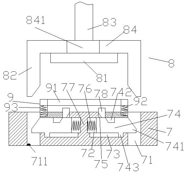
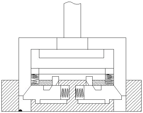
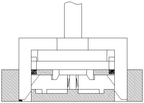
[0020] Such as Figure 1-Figure 4 As shown, a new type of electric shock-proof power supply device of the present invention includes a socket part 8 and a socket part 7 arranged at the lower end of the socket part 8. The socket part 8 includes a connecting rod 84, a power connection 81 and wire 83, both sides of the connecting rod 84 are fixed with downwardly extending oblique insertion rods 82, and the upper end of the socket part 7 is symmetrical to the left and right and is extended upwardly with a carriage 9, each of the sliding The upper end of the frame 9 is provided with a limit block 94, and each of the slide frames 9 is provided with a lower pressure groove 93, and each of the lower pressure grooves 93 is provided with a first compression spring 92, and the two lower pressure grooves 93 are provided with a first compression spring 92. A conductive piece 91 is connected to the sliding fit between the pressure grooves, and the upward extension end of the first compressi...


PUM


Abstract

The invention discloses a novel electric shock prevention power supply device which comprises an inserting portion and a socket portion arranged at the lower end of the inserting portion. A connection rod, a power connection piece and a wire are arranged in the inserting portion, inclined inserting rods extending downwards are fixedly arranged on two sides of the connection rod, slide frames are arranged in the upper end of the pocket portion in a left-right symmetrical and upwards-extending mode, a limit block is arranged at the upper end of each slide frame, a pressing-down groove is formed in each slide frame, a first pressure spring is arranged on the bottom surface of each pressing-down groove, a conducting plate is in slide fit connection between the two pressing-down grooves, the upwards-extending ends of the first pressure springs are fixedly connected with and in pressing-down match with the bottom surface of the conducting plate, inserting holes are formed in the socket portion corresponding to the lower ends of the inclined inserting rods, slide grooves are arranged in the socket portion and between the inserting holes in a left-right symmetrical mode, a stopping plate fixedly connected with the socket portion is arranged between the slide grooves, a penetrating hole which penetrates through a top wall of the socket portion and is communicated with an area between the slide frames is formed in the upper end of each slide groove, and conducting pins are arranged in the penetrating holes. The novel electric shock prevention power supply device disclosed by the invention has a simple structure, can be powered on automatically in insertion, can be automatically powered off when being pulled out and has higher power supply safety and lower use cost.

Description

technical field [0001] The invention relates to the field of electric power technology, in particular to a novel electric shock-proof power supply device. Background technique [0002] As a frequently used electrical equipment, the safety performance of the power supply device is directly related to the personal safety of various groups of people. In daily work and life, we often encounter the need to use the power supply stand to provide power for the power supply head. However, the power supply stand is still energized when it is not in use. Some conductive sheets in the power supply stand are set relatively outside, so that It is easy to cause the danger of electric shock caused by accidental contact of personnel, and there is a great potential safety hazard. Contents of the invention [0003] The technical problem to be solved by the present invention is to provide a novel electric shock-proof power supply device, which can solve the above-mentioned problems in the pr...

Claims


Application Information

Patent Timeline
Patent Type & Authority Applications(China)
IPC IPC(8): H01R13/46H01R13/66H01R13/703H01R13/717
CPCH01R13/46H01R13/66H01R13/6683H01R13/703H01R13/717
Inventor 俞亮亮
Owner 大航电科(江苏)新能源有限公司
Why Eureka
Try Eureka