
Shields and Electronics

A technology for electronic equipment and shielding covers, which is applied in the fields of magnetic field/electric field shielding, electrical components, etc., can solve the problems that the height of the module cannot be increased, the risk of module breakage is increased, etc., and achieves simple design, low cost, and enhanced bending resistance. Effect

Active Publication Date: 2019-07-26
LENOVO (BEIJING) LTD
View PDF2 Cites 0 Cited by
  • Summary
  • Abstract
  • Description
  • Claims
  • Application Information

AI Technical Summary

Problems solved by technology

At the same time, the height of the module cannot be increased. Under the premise of the same manufacturing cost, the industry generally uses very thin PCB circuit boards, but this will cause a significant increase in the risk of module breakage during the actual mass production assembly process.

Method used


Image

  • Shields and Electronics
  • Shields and Electronics
  • Shields and Electronics

Examples


Embodiment Construction

[0028] In order to make the purpose, technical solutions and advantages of the present disclosure clearer, the present disclosure will be further described in detail below in conjunction with specific embodiments and with reference to the accompanying drawings. In the drawings, the same reference numerals correspond to the same elements. However, the invention admits of many different embodiments, and should not be construed as limiting the invention to the described embodiments; rather, by providing exemplary embodiments of the invention so that this disclosure will be thorough and complete, and to the knowledge of those skilled in the art. personnel fully convey the concept of the invention.

[0029] In this disclosure, the terms "comprising", "comprising", "having", "containing", "provided with" and their derivatives are meant to include but not to limit; the term "or" is inclusive and means " and / or".

[0030] In this specification, the various embodiments described be...


PUM


Abstract

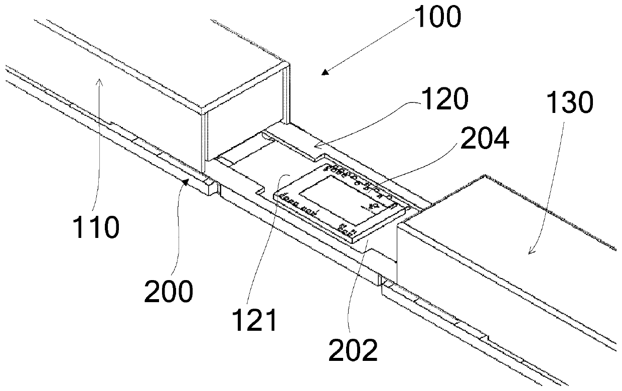
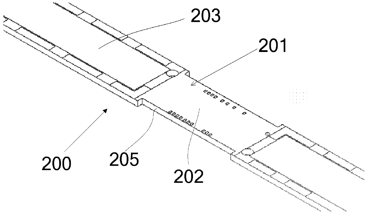
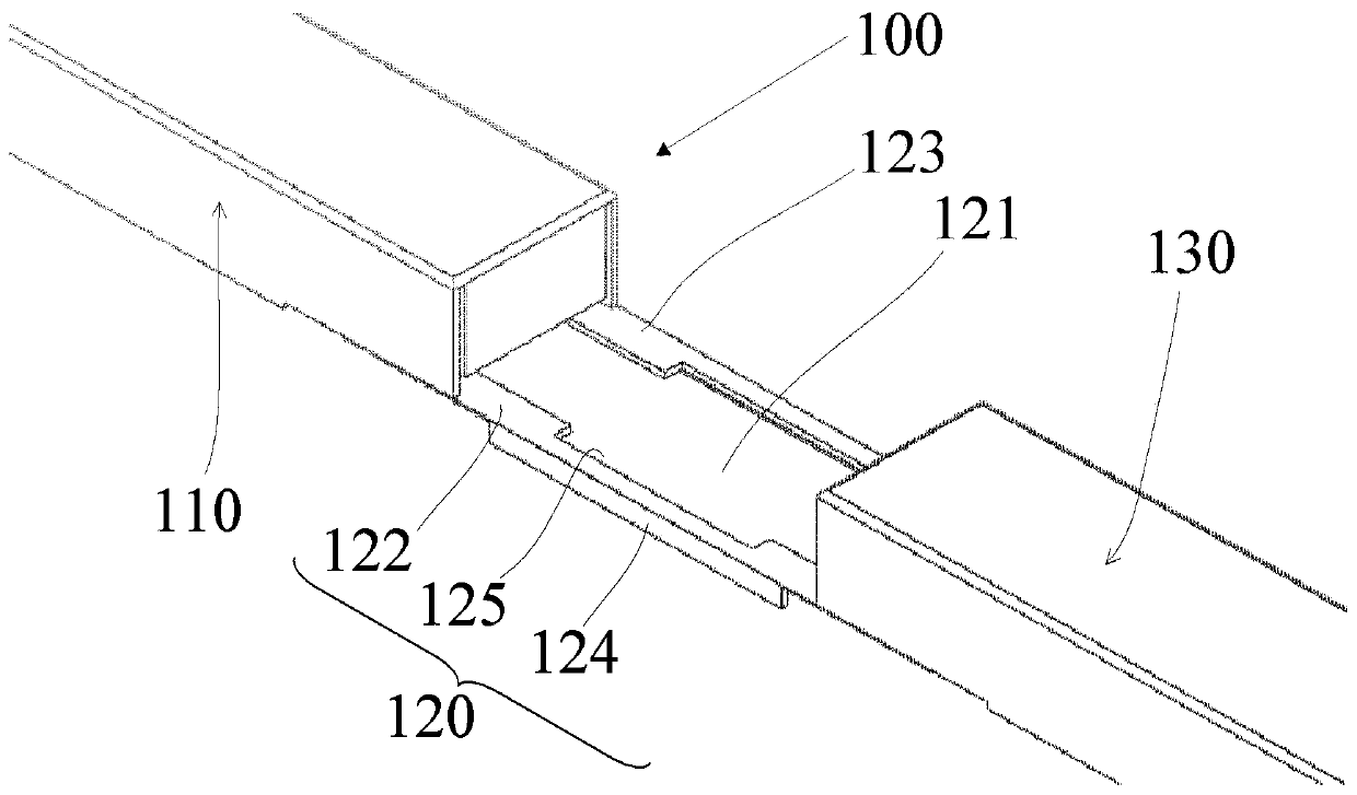
The invention provides a shielding case and an electronic device comprising the shielding case. The electronic device comprises a circuit board, a plurality of electronic elements installed in an electronic element mounting area of the circuit board, and a camera module installed in a camera mounting area of the circuit board. The shielding case comprises a case body portion and a structural reinforcing portion, wherein the case body portion is configured to be mounted on the circuit board and to cover a part of the plurality of electronic elements; and the structure reinforcing portion is configured to extend at least along the surface of the circuit board so as to at least partially support the camera module.

Description

technical field [0001] Embodiments of the present invention generally relate to electronic products, and more particularly, relate to a shield capable of enhancing the bending strength of a camera module and an electronic device including the shield. Background technique [0002] Currently, with the development trend of thinner and lighter electronic devices such as notebook computers, the borders of such electronic devices are becoming narrower and narrower. Correspondingly, the width of the camera module mounted on the electronic device is changed from the conventional 8mm or Above 6mm, gradually develop to 4mm, 3mm, 2mm. At the same time, the height of the module cannot be increased. Under the premise of the same manufacturing cost, the industry generally uses very thin PCB circuit boards, but this will cause a significant increase in the risk of module breakage during the actual mass production assembly process. Contents of the invention [0003] It is an object of th...

Claims


Application Information

Patent Timeline
Patent Type & Authority Patents(China)
IPC IPC(8): H05K9/00
CPCH05K9/0024
Inventor 于宙刘杰王智虎
Owner LENOVO (BEIJING) LTD
Learn More