Cervical vertebra drag hook

A cervical spine and left arm clamping technology, applied in the field of cervical spine retractors, can solve the problems of increasing the difficulty of operation, reducing the operation efficiency, limiting the operation space, etc., and achieves the effect of broadening the operation field, increasing the retraction distance, and reducing the occlusion.

Active Publication Date: 2017-06-20
WEST CHINA HOSPITAL SICHUAN UNIV
View PDF7 Cites 1 Cited by
  • Summary
  • Abstract
  • Description
  • Claims
  • Application Information

AI Technical Summary

Problems solved by technology

Patent document CN 201782785 U discloses an adjustable multifunctional spinal retractor. Although it can pull the surrounding tissue, the forceps handle above the retractor will block the surgical field of view during the operation, limit the operation space, increase the difficulty of operation, and reduce the risk of surgery. efficiency

Method used


Image

  • Cervical vertebra drag hook
  • Cervical vertebra drag hook
  • Cervical vertebra drag hook

Examples


Embodiment Construction

[0036] In order to make the object, technical solution and advantages of the present invention clearer, the present invention will be further described in detail below in conjunction with the accompanying drawings.

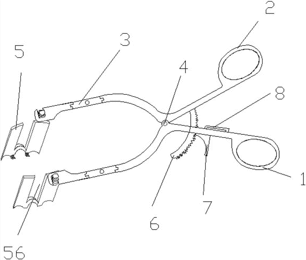
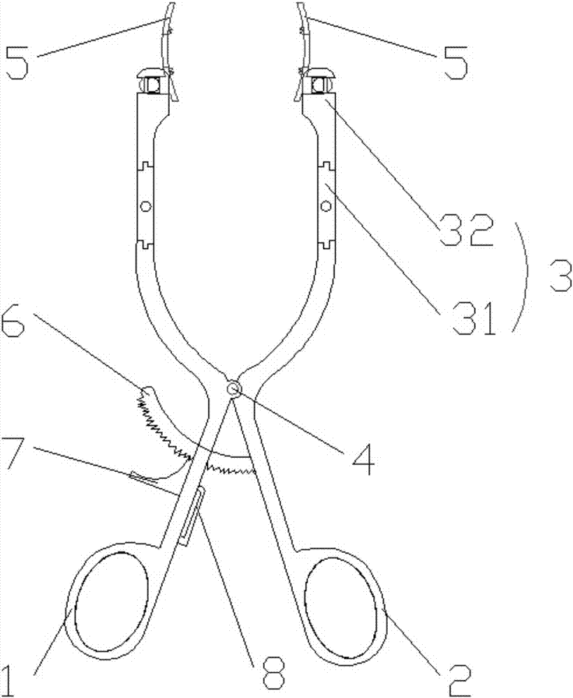
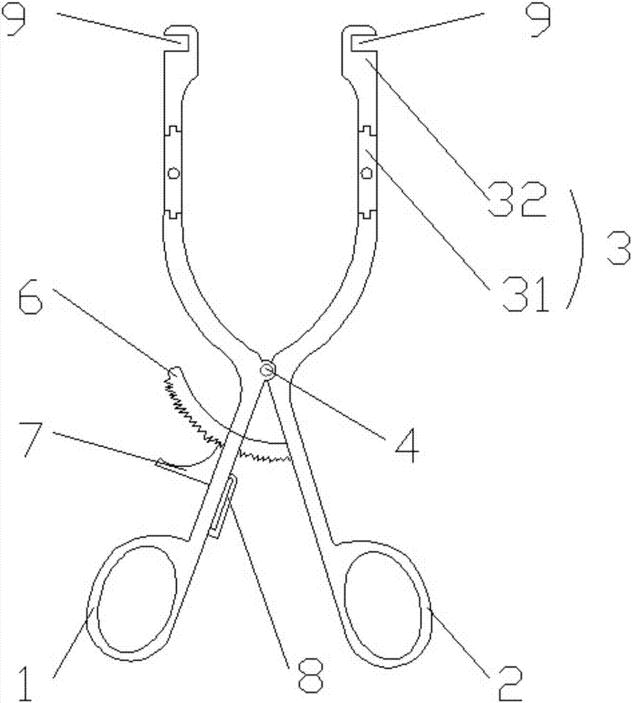
[0037] Such as figure 1 , 2 As shown, the cervical retractor disclosed by the present invention includes a left clamp arm 1, a right clamp arm 2, a movable arm 3 and a pull hook 5, the left clamp arm 1 and the right clamp arm 2 are hinged by a pivot 4, the left clamp arm 1 and the right clamp arm Arm 2 front ends are respectively hinged with movable arm 3, and the rotation direction of movable arm 3 is perpendicular to the rotation direction of left clamp arm 1 and right clamp arm 2. The movable arm 3 includes a first connecting rod 31 and a second connecting rod 32, the front ends of the left clamping arm 1 and the right clamping arm 2 are respectively hinged with one end of the first connecting rod 31, and the other end of the first connecting rod 31 is connect...


PUM


Abstract

The invention relates to a cervical vertebra drag hook which comprises a left clamp arm, a right clamp arm, a moveable arm and a drag hook, wherein the left clamp arm is hinged with the right clamp arm through a pivot; the moveable arm is respectively hinged with the front ends of the left clamp arm and the right clamp arm; a rotating direction of the moveable arm is vertical to the rotating directions of the left clamp arm and the right clamp arm; a notch with an upward opening is formed between a first baffle sheet and a second baffle sheet; the second baffle sheet is located at the front end of the first baffle sheet; the drag hook is located under the moveable arm; the notch is located on the outer side of the moveable arm; at least two inward toothed bulges are arranged at the bottom of the first baffle sheet and the second baffle sheet. A free end of the drag hook in the cervical vertebra drag hook extends toward the front end and the limitation to the surgery operation space is reduced; the intervertebral disc surgery operation can be performed through the notch on the drag hook; in a use process, the inward toothed bulges at the bottom of the baffle sheets are blocked at the lateral border of the centrum, so that the stability of the drag hook is increased; the toothed bulges are arranged inward, so that the pulling distance of the two drag hooks on the left and right sides can be increased and the operation space is further exposed.

Description

technical field [0001] The invention relates to the technical field of medical instruments, in particular to a cervical retractor. Background technique [0002] In orthopedic cervical spine surgery, cervical retractors are usually used to expose the surgical area for stretching tissue, so as to facilitate surgery. Patent document CN 201782785 U discloses an adjustable multifunctional spinal retractor. Although it can pull the surrounding tissue, the forceps handle above the retractor will block the surgical field of view during the operation, limit the operation space, increase the difficulty of operation, and reduce the risk of surgery. efficiency. Contents of the invention [0003] The present invention aims to provide a retractor for the cervical spine, one end of the retractor is connected to the front end of the clamp arm, and the free end of the retractor extends toward the front end, so as to avoid the restriction of the operation space by the clamp arm, and at the...

Claims


Application Information

Patent Timeline
Patent Type & Authority Applications(China)
IPC IPC(8): A61B17/02
CPCA61B17/0206A61B17/025A61B2017/0256
Inventor 马立泰杨毅刘浩
Owner WEST CHINA HOSPITAL SICHUAN UNIV
Why Eureka
Try Eureka