
Infrared riveting mechanism

A riveting mechanism and infrared technology, applied in the field of infrared riveting mechanism, can solve the problems of riveting parts that cannot be riveted, low riveting accuracy, etc., achieve high riveting accuracy, reduce volume, and improve riveting accuracy

Pending Publication Date: 2017-06-20
儒拉玛特自动化技术(合肥)有限公司
View PDF0 Cites 2 Cited by
  • Summary
  • Abstract
  • Description
  • Claims
  • Application Information

AI Technical Summary

Problems solved by technology

[0003] The present invention proposes an infrared riveting mechanism to solve the problems in the prior art that some parts in a narrow space cannot be riveted and the riveting precision is not high

Method used


Image

  • Infrared riveting mechanism

Examples


Embodiment Construction

[0015] The following will clearly and completely describe the technical solutions in the embodiments of the present invention with reference to the accompanying drawings in the embodiments of the present invention. Obviously, the described embodiments are only some, not all, embodiments of the present invention. Based on the embodiments of the present invention, all other embodiments obtained by persons of ordinary skill in the art without making creative efforts belong to the protection scope of the present invention.

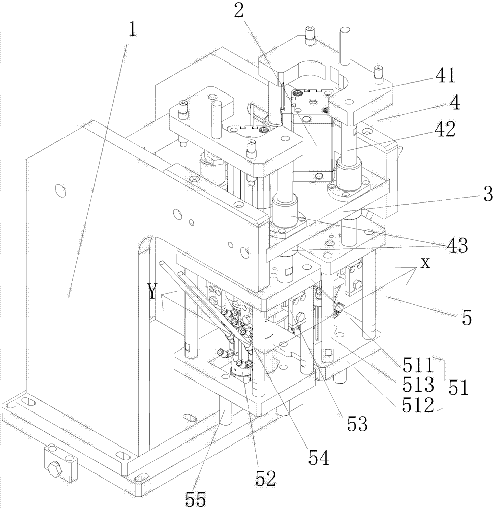
[0016] Such as figure 1 As shown, an infrared riveting mechanism proposed by the present invention includes a frame 1, a driving device 2, a fixing plate 3 and a riveting device 5, the fixing plate 3 is arranged on the top of the frame 1, and the driving device 2 is arranged above the fixing plate 3 , The driving device 2 is a pneumatic cylinder. A riveting device 5 is provided below the fixed plate 3, and a through hole is provided on the fixed plate 3. The ...


PUM


Abstract

The invention discloses an infrared riveting mechanism, which comprises a frame, a driving device, a fixing plate and a riveting device, the fixing plate is arranged on the top of the frame, a driving device is arranged above the fixing plate, a riveting device is arranged under the fixing plate, and a fixed A through hole is opened on the board, and the driving device includes a movable end and a fixed end. The movable end of the driving device passes through the through hole and is connected to the top drive of the riveting device. The riveting device includes a fixed frame, an infrared riveting machine, an X-axis displacement adjustment mechanism and The Y-axis displacement adjustment mechanism, the X-axis displacement adjustment mechanism and the Y-axis displacement adjustment mechanism are respectively arranged on the inner top of the fixed frame, and the top of the infrared riveting machine is respectively connected with the X-axis displacement adjustment mechanism and the Y-axis displacement adjustment mechanism. Compared with the prior art, the invention not only can rivet parts in some narrow spaces, but also has high riveting precision.

Description

technical field [0001] The invention relates to the technical field of riveting, in particular to an infrared riveting mechanism. Background technique [0002] The non-detachable connection that uses rivets to connect more than two riveted parts together is called rivet connection, or riveting for short. At present, there are two commonly used riveting methods. For metal materials, riveting machines are usually used for riveting, and for plastic materials, external heating is generally used for riveting, which is referred to as hot riveting. However, due to the pressure plate structure, the hot riveting machine has a large volume. For some parts in a small space, the riveting head may interfere with the product and cannot be riveted, and the riveting accuracy of the existing hot riveting machine is not high. Therefore, it is necessary to propose a new technical solution to solve these problems. Contents of the invention [0003] The invention proposes an infrared rivetin...

Claims


Application Information

Patent Timeline
IPC IPC(8): B29C65/14
CPCB29C65/1412
Inventor 张建刚
Owner 儒拉玛特自动化技术(合肥)有限公司
Learn More