A method for forming inner circumferential reinforcing ribs of a composite material shell

A technology for hoop stiffeners and composite materials is applied in the field of forming hoop stiffeners in composite material shells, which can solve the problems of easy falling off, inability to ensure the quality of the bonding interface, and inaccurate positioning.

Active Publication Date: 2018-12-07
HUBEI SANJIANG AEROSPACE GRP HONGYANG ELECTROMECHANICAL
View PDF5 Cites 0 Cited by
  • Summary
  • Abstract
  • Description
  • Claims
  • Application Information

AI Technical Summary

Problems solved by technology

[0004] Aiming at the problems existing in the prior art, the embodiment of the present invention provides a method for forming a circular reinforcing rib in a composite material shell, which is used to solve the problem of inaccurate positioning when combining large-size composite material shells and reinforcing ribs in the prior art. Accurate and easy to fall off lead to technical problems that cannot ensure the quality of the bonding interface

Method used


Image

  • A method for forming inner circumferential reinforcing ribs of a composite material shell
  • A method for forming inner circumferential reinforcing ribs of a composite material shell

Examples


Embodiment 2

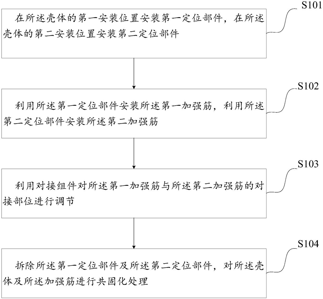
[0054] In practical applications, when the circumferential reinforcement ribs of the composite shell are formed by the method provided in the first embodiment, the details are as follows:

[0055] Installing a first positioning component at the first position of the housing, and before installing a second positioning component at the second position of the housing, the method further includes: laying a prepreg in the housing forming mold After the mold is closed, the shell is preformed at a temperature of 110°C. The two ends of the shell molding die are provided with metal baffles, and the two ends of the baffles are respectively provided with assembly holes of the first positioning component and the second positioning component for installation at the first position of the shell The first positioning component is installed at the second position of the housing. Wherein, the first position of the shell is one side of the axis of the hoop stiffener, and the second position of the...

Embodiment 3

[0069] In actual applications, when using the method provided in the first embodiment to shape the circumferential stiffeners of another composite shell, the details are as follows:

[0070] Installing a first positioning component at the first position of the housing, and before installing a second positioning component at the second position of the housing, the method further includes: laying a prepreg in the housing forming mold After the mold is closed, the shell is preformed at a temperature of 120°C. The two ends of the shell molding die are provided with metal baffles, and the two ends of the baffles are respectively provided with assembly holes of the first positioning component and the second positioning component for installation at the first position of the shell The first positioning component is installed at the second position of the housing. Wherein, the first position of the shell is one side of the axis of the hoop stiffener, and the second position of the shell...


PUM

PropertyMeasurementUnit
diameteraaaaaaaaaa
lengthaaaaaaaaaa
diameteraaaaaaaaaa

Abstract

The invention provides a method for forming a circular reinforcing rib in a composite material shell, the reinforcing rib includes: a first reinforcing rib and a second reinforcing rib, and the method includes: installing a second reinforcing rib at a first position of the shell A positioning component, a second positioning component is installed at a second position of the housing; the first reinforcing rib is installed by using the first positioning component, and the second reinforcing rib is installed by using the second positioning component; Use the docking assembly to adjust the docking position of the first reinforcing rib and the second reinforcing rib; remove the first positioning component and the second positioning component, and perform a joint operation on the housing and the reinforcing rib Curing treatment; wherein, the reinforcing rib and the shell are made of the same composite material; the shell has a diameter of at least 2m and a length of at least 4m.

Description

Technical field [0001] The invention belongs to the technical field of composite material processing, and in particular relates to a method for forming inner circumferential reinforcing ribs of a composite material shell. Background technique [0002] Lightweight design and manufacturing technology is one of the key research and development directions of product bearing structures in the aerospace field. Composite materials have a series of advantages such as low density, high strength and high modulus, acid and alkali corrosion resistance, and can replace traditional metal materials to achieve bearing functions and Lightweight targets have broad application prospects in the field of aerospace products. [0003] As the main bearing structure of the composite shell, the molding quality of the inner circumferential stiffener is one of the important factors to realize the bearing function of the shell. The forming quality of the inner ring stiffener mainly includes the bearing streng...

Claims


Application Information

Patent Timeline
Patent Type & Authority Patents(China)
IPC IPC(8): B29C70/34B29C70/54B29L31/30
CPCB29C70/342B29C70/54B29L2031/3097
Inventor 方登科黄永勇沈亚东陈伟付忠奎董萌
Owner HUBEI SANJIANG AEROSPACE GRP HONGYANG ELECTROMECHANICAL
Why Eureka
Try Eureka