Nozzle for polycrystalline silicon reduction furnaces with 48 pairs of sticks

A technology of polysilicon and reduction furnace, applied in the direction of silicon compounds, inorganic chemistry, non-metallic elements, etc., can solve the problems of increasing the complexity of the temperature field and flow field of the reduction furnace, and achieve the effect of sufficient and uniform distribution of the reduction reaction

Active Publication Date: 2017-06-20
ASIA SILICON QINGHAI
View PDF5 Cites 3 Cited by
  • Summary
  • Abstract
  • Description
  • Claims
  • Application Information

AI Technical Summary

Problems solved by technology

[0004] When the volume of the polysilicon reduction furnace increases to 48 pairs of rods, the complexity of the temperature field and flow field in the reduction furnace increases

Method used


Image

  • Nozzle for polycrystalline silicon reduction furnaces with 48 pairs of sticks
  • Nozzle for polycrystalline silicon reduction furnaces with 48 pairs of sticks
  • Nozzle for polycrystalline silicon reduction furnaces with 48 pairs of sticks

Examples


Embodiment 1

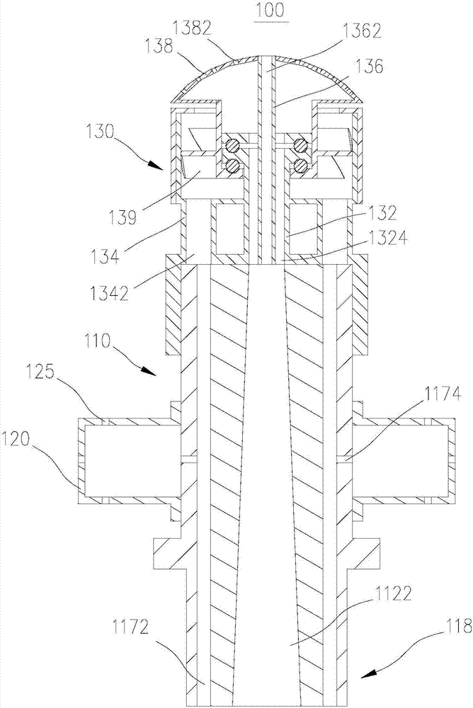
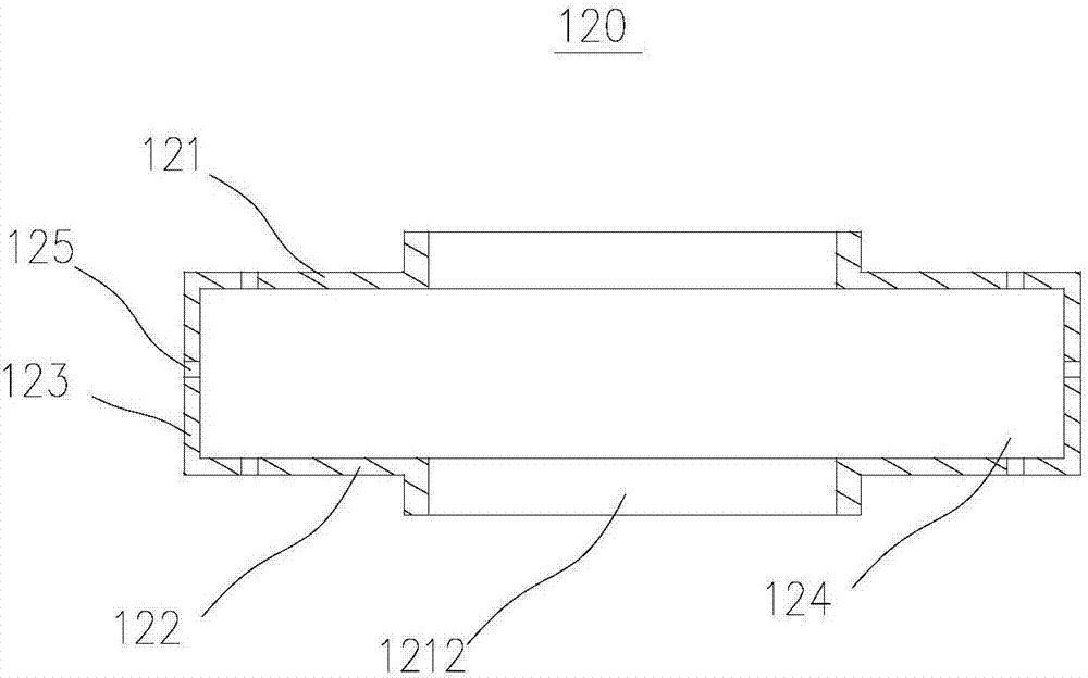
[0044] This embodiment provides a nozzle 100, such as figure 1 , this nozzle 100 is used to inject from the chassis 210 ( Figure 8 ) material gas is charged into the reduction furnace ( Figure 7 ) to carry out the reduction reaction, mainly including the core body 110, the shunt cover 120 and the nozzle 100. The shunt cover 120 is a cylindrical shell structure, which is sheathed on the core body 110 , and the nozzle 100 is connected to the gas outlet end 116 of the core body 110 . The entire nozzle 100 utilizes the spray head 130 and the shunt cover 120 to charge the material gas into the reduction furnace for reaction.

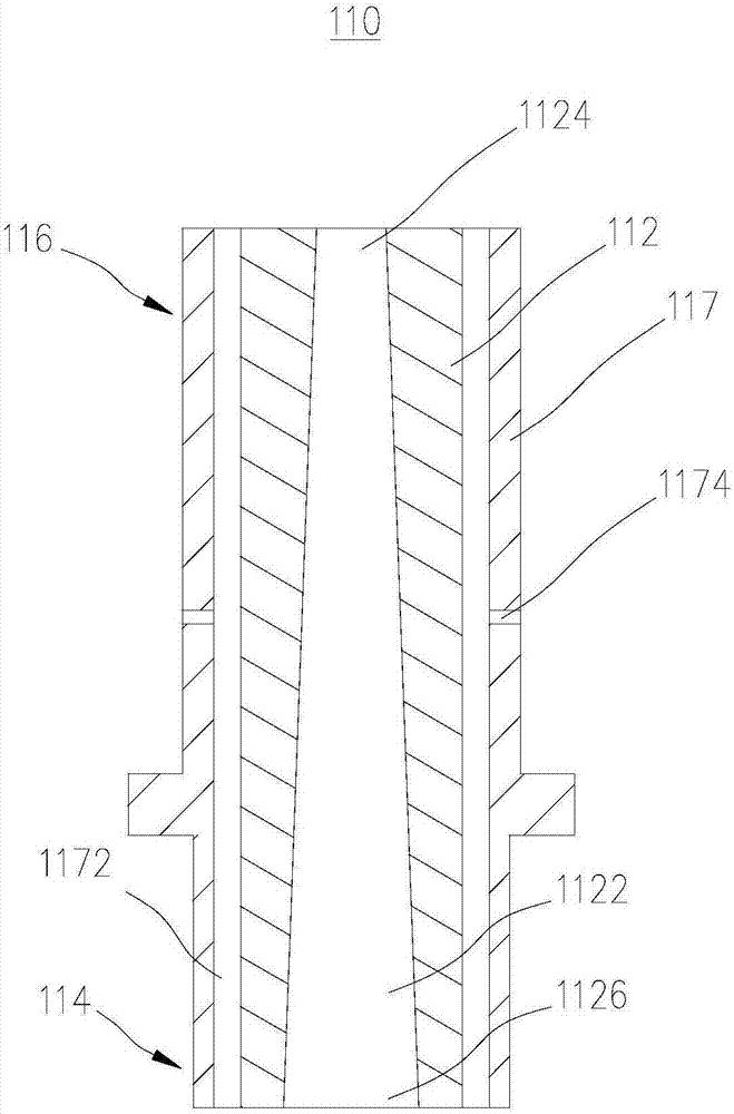
[0045] Such as figure 1 and 2 , the core 110 includes a first inner tube 112 and a first outer tube 117 , and the first outer tube 117 is sheathed on the first inner tube 112 . The first inner tube 112 is provided with a through hole, and the through hole extends along the length direction of the first inner tube 112 to form a main channel 1122 , and t...

Embodiment 2

[0052] Such as Figure 7 and Figure 8 , the present embodiment provides a 48-pair rod polysilicon reduction furnace 200, which includes 48 pairs of rods (not shown in the figure), the chassis 210 and the nozzle 100 provided in Embodiment 1. An air outlet is provided on the chassis 210 , and the nozzle 100 is connected to the air outlet through the connecting portion 118 .

[0053] Since the structures of other components of the reduction furnace are relatively common in the prior art, this embodiment does not introduce the specific structure of the reduction furnace in detail.

[0054] Such as figure 1 , Figure 7 and Figure 8 , The working principle of the 48-pair polysilicon reduction furnace 200 is as follows: the material gas first comes to the chassis 210, and enters the main channel 1122 and the auxiliary channel 1172 from the gas outlet of the chassis 210. The gas in the main channel 1122 is accelerated and enters the shower head 130 from the gas outlet 1124, and...


PUM


Abstract

The invention provides a nozzle for polycrystalline silicon reduction furnaces with 48 pairs of sticks. The nozzle belongs to the production field of polycrystalline silicon. The nozzle mainly comprises a cylinder core. The core consists of a first inner tube and a first outer tube. The first outer tube is set and covered on the first inner tube. The first inner tube comprises a main channel. The flow area of the air outlet of the main channel is smaller than the air inlet. The gap between the first outer tube and the first inner tube forms an auxiliary channel. The core is installed on a chassis through an interconnecting piece. Due to the flow area of the air inlet is larger than the flow area of the air outlet, air is passing through the main channel with an increasingly faster speed and eventually reaches the top of the reduction furnace. After passing through the auxiliary channel, a part of the air in the auxiliary channel gets to the middle of the reduction furnace, and the other part of the air gets to the bottom of the reduction furnace through a plurality of side vent holes on the first outer tube. The material gas can be evenly distributed in the entire reduction furnace, which leads to the fully performing of the reduction reaction.

Description

technical field [0001] The invention relates to the field of polysilicon production, in particular to a nozzle for a 48-pair polysilicon reduction furnace and the polysilicon reduction furnace. Background technique [0002] At present, more than 85% of the world's polysilicon is produced by the improved Siemens method. The improved Siemens method is a chemical method. Firstly, metallurgical silicon (purity required to be above 99.5%) is synthesized with hydrogen chloride (HCl) to produce trichlorosilane gas (SiHCl3, hereinafter referred to as TCS), which is easy to purify, and then the TCS is rectified and purified. , and finally convert the high-purity TCS into high-purity polysilicon by reduction reaction and chemical vapor deposition (CVD). [0003] The reduction reaction needs to be carried out in the polysilicon reduction furnace. Generally, the mixed material gas of hydrogen and TCS is passed into the reduction furnace through the chassis, and the reduction reaction o...

Claims


Application Information

Patent Timeline
Patent Type & Authority Applications(China)
IPC IPC(8): C01B33/035
CPCC01B33/035
Inventor 唐国强张宝顺宗冰蔡延国惠庆华鲍守珍王体虎
Owner ASIA SILICON QINGHAI
Why Eureka
Try Eureka