

Camera lens set
A camera lens and lens technology, applied in optical elements, optics, instruments, etc., can solve problems such as unfavorable shooting of distant objects, lack of design freedom, and difficulty in meeting the needs of high imaging performance, and achieve good imaging quality and module. The effect of small size and long effective focal length
- Summary
- Abstract
- Description
- Claims
- Application Information
AI Technical Summary
Problems solved by technology
Method used
Image

Examples
Embodiment 1
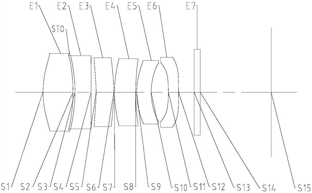
[0068] First refer to Figure 1 to Figure 5 An imaging lens group according to Embodiment 1 of the present application will be described.
[0069] figure 1 It is a schematic diagram showing the structure of the imaging lens group in Embodiment 1. like figure 1 As shown, the imaging lens group includes 6 lenses. The six lenses are the first lens E1 with object side S1 and image side S2, the second lens E2 with object side S3 and image side S4, the third lens E3 with object side S5 and image side S6, and the third lens E3 with object side S5 and image side S6. A fourth lens E4 with a side S7 and an image side S8, a fifth lens E5 with an object side S9 and an image side S10, and a sixth lens E6 with an object side S11 and an image side S12. The first lens E1 to the sixth lens E6 are arranged in order from the object side to the image side of the imaging lens group. The first lens E1 may have positive power, and its object side S1 may be convex; the second lens E2 may have ne...
Embodiment 2
[0081] Refer to the following Figure 6 to Figure 10 An imaging lens group according to Embodiment 2 of the present application will be described. In addition to the parameters of each lens of the imaging lens group, such as the radius of curvature, thickness, material, conic coefficient, effective focal length, axial distance, and higher-order coefficients of each lens, in this embodiment 2 The arrangement structure of the imaging lens groups described in the following embodiments is the same as that of the imaging lens groups described in Embodiment 1. In this embodiment and the following embodiments, for the sake of brevity, descriptions similar to those in Embodiment 1 will be omitted.
[0082] Image 6 It is a schematic diagram showing the structure of the imaging lens group of Embodiment 2. The imaging lens group includes a first lens E1 , a second lens E2 , a third lens E3 , a fourth lens E4 , a fifth lens E5 and a sixth lens E6 from the object side to the image side...
Embodiment 3
[0095] Refer to the following Figure 11 to Figure 15 An imaging lens group according to Embodiment 3 of the present application will be described.
[0096] Figure 11 It is a schematic diagram showing the structure of the imaging lens group of Embodiment 3. The imaging lens group includes a first lens E1 , a second lens E2 , a third lens E3 , a fourth lens E4 , a fifth lens E5 and a sixth lens E6 from the object side to the image side.
[0097] Table 7 below shows the effective focal lengths f1 to f6 of the first to sixth lenses E1 to E6, the total effective focal length f of the imaging lens group, the total length TTL of the imaging lens group, and half the maximum field of view HFOV of the imaging lens group .
[0098]
[0099]
[0100] Table 7
[0101] Table 8 shows the surface type, curvature radius, thickness, material and conic coefficient of each lens in the imaging lens group in this embodiment.
[0102] face number surface type radius of cur...
PUM
 Abstract
Description
Claims
Application Information