
Periscopic optical imaging system, camera module and electronic device

An optical imaging system and optical system technology, applied in the field of periscope optical imaging system, camera module and electronic device, can solve the problems of adding lenses, thick electronic devices, and not satisfying the thinning and miniaturization of electronic devices, etc. Achieve the effect of reducing thickness and long effective focal length

Pending Publication Date: 2022-05-06
HUAWEI TECH CO LTD
View PDF0 Cites 0 Cited by
  • Summary
  • Abstract
  • Description
  • Claims
  • Application Information

AI Technical Summary

Problems solved by technology

[0003] However, during the process of implementing this application, the inventors found that there are at least the following problems in the prior art: the camera module of most electronic devices has a telephoto function, resulting in a relatively thick electronic device, which does not meet the requirements for thinning and miniaturization of electronic devices For example, the vertical transmission telephoto lens realizes the telephoto function by adopting the coaxial design of multiple transmission lenses. Due to the thickness and space limitation of the vertical transmission telephoto lens, the focal length that can be achieved is small. In order to achieve a larger focal length, it needs Increase the number of lenses, increase the cost of the lens and the thickness of the lens

Method used


Image

  • Periscopic optical imaging system, camera module and electronic device
  • Periscopic optical imaging system, camera module and electronic device
  • Periscopic optical imaging system, camera module and electronic device

Examples


no. 1 example

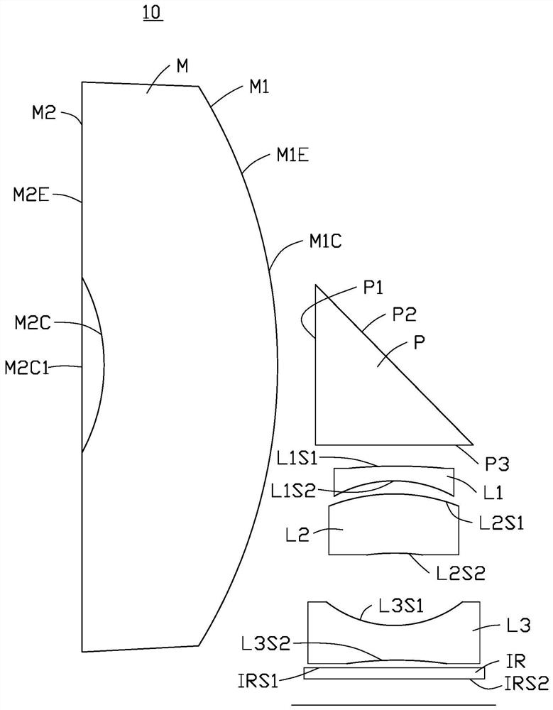
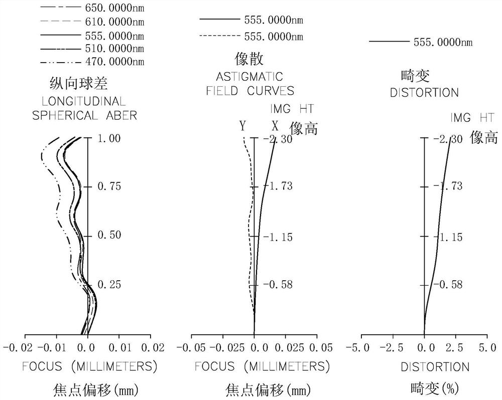
[0122] Please refer to figure 1 The periscope optical imaging system 10 of the first embodiment includes an integral catadioptric lens M, a light redirecting element P, a first lens L1 with negative refractive power, and a first lens L1 with positive refractive power from the object side to the image side. The second lens L2, the third lens L3 with negative refractive power, and an infrared filter IR.

[0123] The integrated catadioptric lens M has an object side M2 ​​and an image side M1, the object side M2 ​​has a light blocking part M2C1, a first transmission part M2E and a second reflection part M2C, and the image side M1 has a first reflection part M1E and a second transmission part M1C. The light blocking part M2C1 is located at the near optical axis of the object side M2 ​​and is a plane, the first transmission part M2E is located at the near circumference of the object side M2 ​​and is a plane, and the second reflection part M2C is located at the near optical axis of ...

no. 2 example

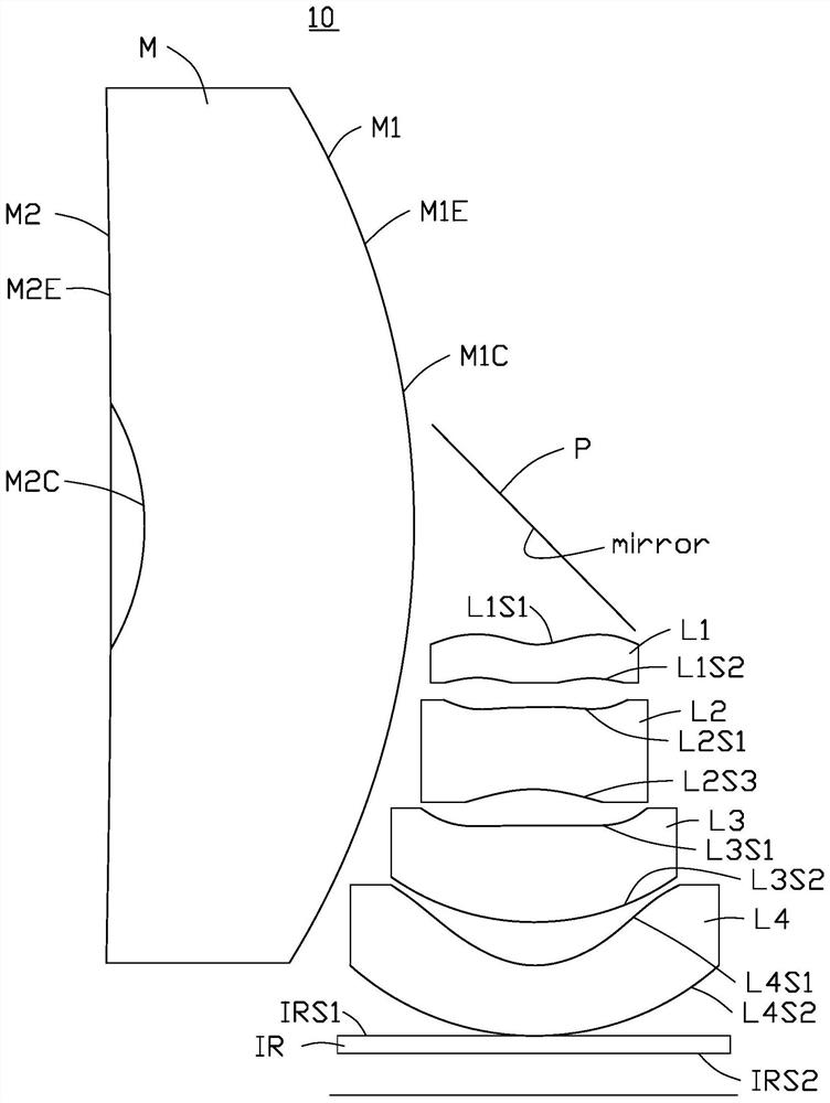
[0144] Please refer to image 3 , the periscope optical imaging system 10 of the second embodiment includes an integral catadioptric lens M, a light redirecting element P, a first lens L1 with negative power, and a lens with negative power from the object side to the image side. The second lens L2, the third lens L3 with positive power, the fourth lens L4 with negative power, and an infrared filter IR.

[0145] The integrated catadioptric lens M has an object side M2 ​​and an image side M1, the object side M2 ​​has a first transmission part M2E and a second reflection part M2C, and the image side M1 has a first reflection part M1E and a second transmission part M1C. The first transmission part M2E is located near the circumference of the object side M2 ​​and is a plane, the second reflection part M2C is located at the near optical axis of the object side M2, the second reflection part M2C is a concave surface, and the first reflection part M1E is located near the circumference...

no. 3 example

[0165] Please refer to Figure 5 The periscope optical imaging system 10 of the third embodiment sequentially includes a first lens L1 with negative refractive power, an integrated catadioptric lens M, a second lens L2 with negative refractive power, from the object side to the image side, A light redirecting member P, a third lens L3 with negative power, a fourth lens L4 with negative power, and an infrared filter IR.

[0166] The integrated catadioptric lens M has an object side M2 ​​and an image side M1, the object side M2 ​​has a first transmission part M2E and a second reflection part M2C, and the image side M1 has a first reflection part M1E and a second transmission part M1C. The first transmission part M2E is located near the circumference of the object side M2 ​​and is a plane, the second reflection part M2C is located at the near optical axis of the object side M2, the second reflection part M2C is a concave surface, and the first reflection part M1E is located near ...


PUM


Abstract

The invention provides a periscopic optical imaging system which comprises an integrated refraction and reflection lens and a light turning piece, the integrated refraction and reflection lens comprises an object side face and an image side face, the object side face is provided with a first transmission part close to the circumference, the image side face is provided with a first reflection part close to the circumference, and the object side face is provided with a second reflection part close to the optical axis. The image side surface is provided with a second transmission part near the optical axis, the first transmission part is arranged around the second reflection part, and the first reflection part is arranged around the second transmission part; the light steering member is arranged on the image side of the integrated refraction and reflection lens. The invention also provides a camera module and an electronic device using the periscopic optical imaging system. According to the periscopic optical imaging system, the integrated refraction and reflection lens is matched with the light steering part, so that the periscopic optical imaging system can realize a longer effective focal length on the premise of meeting miniaturization, lightness and thinness.

Description

technical field [0001] The present application relates to the field of optical technology, in particular to a periscope optical imaging system, a camera module and an electronic device. Background technique [0002] In recent years, with the development of science and technology, smart electronic devices such as mobile phones have become the necessities of ordinary people's life. Users' demand for high-quality photos of mobile phones is becoming stronger and stronger, especially the telephoto shooting function. Zoom in to distinguish details of distant objects. [0003] However, during the process of implementing this application, the inventors found that there are at least the following problems in the prior art: the camera module of most electronic devices has a telephoto function, resulting in a relatively thick electronic device, which does not meet the requirements for thinning and miniaturization of electronic devices For example, the vertical transmission telephoto l...

Claims


Application Information

Patent Timeline
IPC IPC(8): G02B13/00G02B13/18G02B17/08
CPCG02B13/0055G02B13/0065G02B13/0035G02B13/004G02B17/086G02B13/18G02B17/08G02B13/00G02B17/00G02B3/02
Inventor 贾远林姚秀文徐运强金闻嘉
Owner HUAWEI TECH CO LTD
Learn More