Optical imaging lens and imaging equipment

An optical imaging lens and imaging surface technology, applied in the field of imaging lenses, can solve the problems of difficult to meet the requirements of preview distance, reduce the target recognition range, poor imaging effect, etc., and achieve improved imaging performance, clear imaging, and good thermal stability. Effect

Active Publication Date: 2022-07-12
合肥联创光学有限公司
View PDF8 Cites 0 Cited by
  • Summary
  • Abstract
  • Description
  • Claims
  • Application Information

AI Technical Summary

Problems solved by technology

At present, the optical lens used for target recognition in front of the vehicle is often designed for short-distance targets, and its field of view is relatively large. Although this type of lens can image short-distance targets well, it cannot image distant targets. The effect is poor, and the recognition accuracy of medium and long-distance targets cannot be taken into account, which reduces the effective target recognition range and is difficult to meet the requirements of the front preview distance for cars driving at high speeds

Method used


Image

  • Optical imaging lens and imaging equipment
  • Optical imaging lens and imaging equipment
  • Optical imaging lens and imaging equipment

Examples


no. 1 example

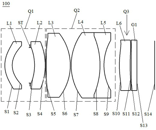
[0084] see figure 1 , is a schematic structural diagram of the optical imaging lens 100 provided by the first embodiment of the present invention. The optical imaging lens 100 sequentially includes from the object side to the imaging surface along the optical axis: a first group Q1 with negative refractive power and a positive refractive power The second group Q2 of 10 degrees, the third group Q3 with positive power, the filter G1.

[0085] The first group Q1 includes a first lens L1 and a second lens L2 in sequence from the object side to the imaging plane along the optical axis. The second group Q2 includes a third lens L3, a fourth lens L4, and a fifth lens L5 in sequence from the object side to the imaging plane along the optical axis. The third group Q3 sequentially includes a sixth lens L6 along the optical axis from the object side to the imaging plane. A stop ST is provided between the first lens L1 and the second lens L2.

[0086] Wherein, the first lens L1 has neg...

no. 2 example

[0101] For a schematic structural diagram of the optical imaging lens 200 provided by the embodiment of the present invention, please refer to Figure 5 , the structure of the optical imaging lens 200 in this embodiment is roughly the same as the structure of the optical imaging lens 100 in the first embodiment, the difference is: the object side S10 of the sixth lens is convex, and the image side S11 is concave; The mechanical back focus between the sixth lens L6 of a lens and the imaging surface S14 is lengthened; and there are differences in the materials of some lenses, the related parameters of each lens, and the air space.

[0102] The relevant parameters of each lens of the optical imaging lens 200 provided in this embodiment are shown in Table 3.

[0103] table 3

[0104]

[0105] Table 4 shows the surface shape coefficients of each aspherical surface in the optical imaging lens 200 in this embodiment.

[0106] Table 4

[0107]

[0108] The distortion graph, MTF...

no. 3 example

[0110] For a schematic structural diagram of the optical imaging lens 300 provided by the embodiment of the present invention, please refer to Figure 9 , the structure of the optical imaging lens 300 in this embodiment is roughly the same as that of the optical imaging lens 100 in the first embodiment, the difference is that the second lens L2 adopts an aspherical lens, and the sixth lens L6 has a negative focal length There are differences in the related parameters and air spacing of the lens, as well as the individual elements of the lens.

[0111] The related parameters of each lens of the optical imaging lens 300 provided in this embodiment are shown in Table 5.

[0112] table 5

[0113]

[0114] Table 6 shows the surface shape coefficients of each aspherical surface of the optical imaging lens 300 in this embodiment.

[0115] Table 6

[0116]

[0117] The distortion curve graph, MTF graph, and axial chromatic aberration graph of the optical imaging lens 300 prov...


PUM


Abstract

The invention discloses an optical imaging lens and an imaging device. The optical imaging lens includes sequentially from the object side to the imaging surface along the optical axis: a first group with negative refractive power, a second group with positive refractive power, A third group with optical power; the first group includes sequentially from the object side to the imaging plane along the optical axis: a first lens with negative power, a second lens with negative power; the second group From the object side to the imaging surface along the optical axis, it includes: a third lens with positive refractive power, a fourth lens with positive refractive power, and a fifth lens with negative refractive power, and the fourth lens and the fifth lens are cemented together a lens; the third group sequentially includes along the optical axis from the object side to the imaging plane: a sixth lens having optical power. The optical imaging lens has the advantages of large aperture, long focal length and small aperture, and can provide high-definition imaging effects at the same time, and can improve the imaging quality and recognition accuracy of distant targets.

Description

technical field [0001] The present invention relates to the technical field of imaging lenses, in particular to an optical imaging lens and an imaging device. Background technique [0002] With the development of autonomous driving technology, ADAS (Advanced Driver Assistant System) has become the standard configuration of many cars; among them, the on-board camera lens, as the key component of ADAS, can sense the road conditions around the vehicle in real time and realize the The performance of functions such as collision warning, lane deviation warning, and pedestrian detection directly affects the safety factor of ADAS. Therefore, the performance requirements for vehicle camera lenses are getting higher and higher. [0003] The optical lens applied to the front of the vehicle carried in ADAS is mainly to identify the situation in front of the vehicle, and it is required to clearly distinguish obstacles at a long distance to realize collision warning. At present, optical ...

Claims


Application Information

Patent Timeline
Patent Type & Authority Patents(China)
IPC IPC(8): G02B13/00G02B13/02G02B13/06G02B13/18G03B30/00
CPCG02B13/0045G02B13/18G02B13/06G02B13/02G02B13/006G03B30/00
Inventor 陈伟建王家贤
Owner 合肥联创光学有限公司
Why Eureka
Try Eureka