Display panel and display device
A display panel and dark display technology, which is applied in nonlinear optics, instruments, optics, etc., can solve problems affecting user experience, reduce the visual effect of the edge of the display panel, etc., and achieve the effect of improving the visual effect
- Summary
- Abstract
- Description
- Claims
- Application Information
AI Technical Summary
Problems solved by technology
Method used
Image
Examples
no. 1 example
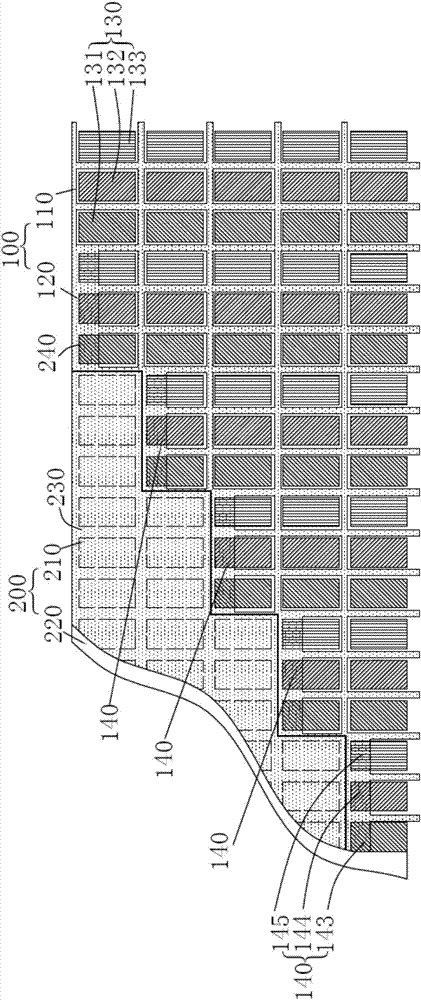
[0036] An embodiment of the present invention provides a display panel. In this embodiment, the display panel is a liquid crystal display panel. Of course, in other embodiments of the present invention, the display panel may also be an OLED panel or other display panels. See figure 1 , the display panel includes a display area 100 and a non-display area 200, the display area 100 is the area where the display panel usually displays images, the display area 100 is shaped, that is, non-rectangular, for example, the display area 100 is circular , ellipse, octagon, hexagon and other non-rectangular shapes to meet the needs of different functions. The non-display area 200 is an area where display panel wiring, drivers, etc. are placed. The display panel as a whole may be irregular or rectangular.
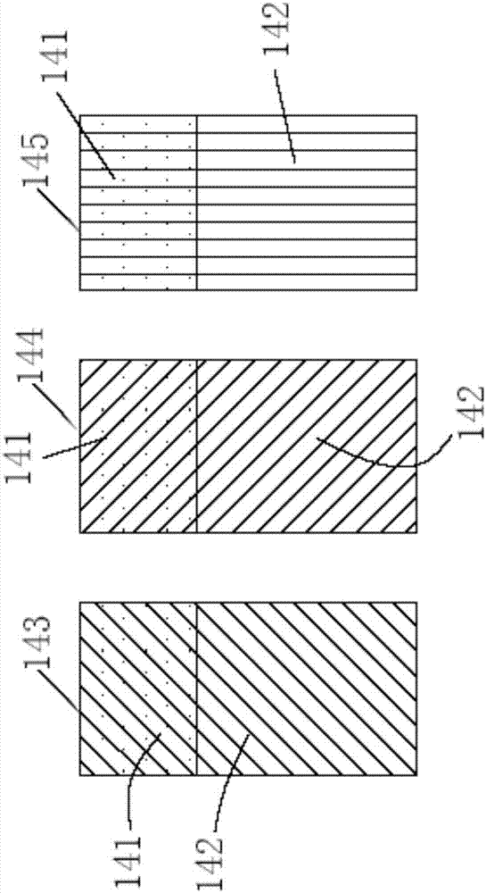
[0037] Since the conventional pixel is a rectangle, the display area 100 must be in a different shape, even if the boundary line between the display area 100 and the non-display area 20...
no. 2 example
[0049] Figure 6 A display panel provided by the second embodiment of the present invention, Figure 6 structure with figure 1 The structures are similar, so the same reference numerals represent the same components. The main difference between this embodiment and the first embodiment is the number of sub-pixels included in the second pixel unit.
[0050] In this embodiment, the dimmed display area 120 includes a plurality of second pixel units 640, the plurality of second pixel units 640 form multiple rows, and each row includes one or more second pixel units 640, Figure 6 Each row in the figure shows a second pixel unit 640, the second pixel unit 640 includes only one sub-pixel, and the sub-pixel can be a red second sub-pixel, a green second sub-pixel, a blue second sub-pixel, etc. , the second black matrix 240 covers part of the sub-pixels, thereby reducing the aperture ratio of the darkened display area 120 , thereby reducing the brightness of the darkened display area ...
no. 3 example
[0052] Figure 7 A display panel provided by the third embodiment of the present invention, Figure 7 structure with figure 1 The structures are similar, so the same reference numerals represent the same components. The main difference between this embodiment and the first embodiment is the darkened display area.
[0053] In this embodiment, the dimmed display area 720 includes a first dimmed display area 721 and a second dimmed display area 722, the first dimmed display area 721 is set adjacent to the normal display area 110, the The second dimmed display area 722 is disposed adjacent to the non-display area 200, the second dimmed display area 722 is located between the non-display area 200 and the first dimmed display area 721, and the first dimmed display area 721 The dark display area 721 is located between the second darkened display area 722 and the normal display area 110, the light transmittance of the second darkened display area 722 is lower than the light transmit...
PUM
 Abstract
Description
Claims
Application Information
 - R&D
- Intellectual Property
- Life Sciences
- Materials
- Tech Scout
- Unparalleled Data Quality
- Higher Quality Content
- 60% Fewer Hallucinations
Browse by: Latest US Patents, China's latest patents, Technical Efficacy Thesaurus, Application Domain, Technology Topic, Popular Technical Reports.
© 2025 PatSnap. All rights reserved.Legal|Privacy policy|Modern Slavery Act Transparency Statement|Sitemap|About US| Contact US: help@patsnap.com


