
Fingerprint sensing module

A fingerprint and sensing surface technology, which is applied in the acquisition/organization of fingerprints/palmprints, character and pattern recognition, instruments, etc.

Active Publication Date: 2017-06-20
GINGY TECH
View PDF5 Cites 57 Cited by
  • Summary
  • Abstract
  • Description
  • Claims
  • Application Information

AI Technical Summary

Problems solved by technology

Since a point on the finger surface will reflect the light beam to multiple positions of the sensing element, one position on the sensing element will simultaneously receive images of multiple finger surface positions, thereby causing the sensing element to sense blurred image, but also makes it easy for the sensing element to misjudge

Method used


Image

  • Fingerprint sensing module
  • Fingerprint sensing module
  • Fingerprint sensing module

Examples


Embodiment Construction

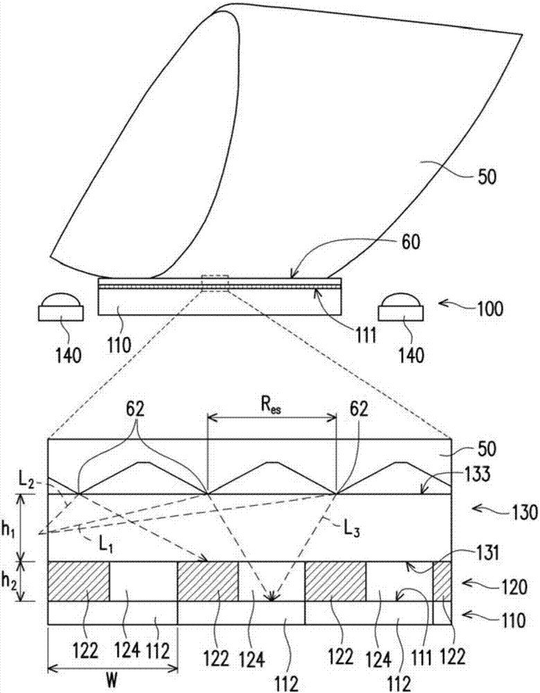
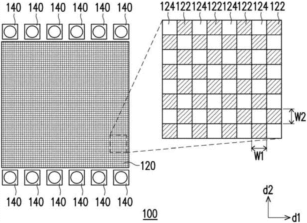
[0050] figure 1 A schematic diagram and partially enlarged schematic diagram of a fingerprint sensing module according to the first embodiment of the present invention. Please refer to figure 1 , the fingerprint sensing module 100 is suitable for sensing the fingerprint 60 of the finger of the subject 50, and the fingerprint sensing module 100 includes a sensing element 110, an optical cover 130, and is disposed between the optical cover 130 and the sensing element 110. The optical alignment layer 120. The sensing element 110 includes a sensing surface 111 , and the optical alignment layer 120 covers the sensing surface 111 . In other words, in the fingerprint sensing module 100 of this embodiment, the light beam is suitable for passing from the optical cover 130 to the sensing element 110 , and the light beam needs to pass through the optical collimation layer 120 before being passed to the sensing element 110 .

[0051] The optical alignment layer 120 of this embodiment i...


PUM


Abstract

A fingerprint sensing module adapted to sense fingerprint of user's finger is provided. The fingerprint sensing module includes a sensing device, an optical cover and an optical-collimating layer located between the sensing device and the optical cover. The sensing device includes a sensing surface, and the optical-collimating layer covers the sensing surface. The optical-collimating layer includes light-blocking areas and light-transmitting areas, and each of the light-transmitting area is surrounded by a part of the light-blocking areas. The optical cover is disposed on the optical-collimating layer, and the optical cover is adapted to contact the user's finger, and the optical cover is adapted to transmit a sensing light from the user's finger to the optical-collimating layer, and the light-blocking areas are adapted to block a portion of the sensing light, and another portion of the sensing light is transmitted to the sensing surface through the light-transmitting areas.

Description

technical field [0001] The invention relates to a sensing device, in particular to a fingerprint sensing module. Background technique [0002] In the past identification technology, the method of fingerprint identification is, for example, to use finger to press the ink and transfer it to paper to form a fingerprint pattern, and then use optical scanning to input it into the computer for file building or comparison. The above-mentioned fingerprint identification method has the disadvantage of being unable to process in real time, and cannot meet the demand for real-time identity authentication in today's society. Therefore, the electronic fingerprint sensing device has become one of the mainstreams of current technological development. [0003] Existing electronic fingerprint sensing devices, for example, use a light source to emit light beams to irradiate the finger surface, and then use optical sensing elements to sense the light beams reflected from the finger surface. ...

Claims


Application Information

Patent Timeline
Patent Type & Authority Applications(China)
IPC IPC(8): G06K9/00
CPCG06V40/1324G06V40/1318G06V40/1329G06V40/1365
Inventor 巫仁杰
Owner GINGY TECH
Learn More