A deodorizing device

A technology for opening and closing devices and cleaning chambers, applied in water supply devices, sanitary equipment for toilets, buildings, etc., can solve the problems of body damage, work efficiency, skin damage, and heavy odor, and achieve simple structure and reduce work intensity , Reduce the effect of manual operation

Active Publication Date: 2017-12-01
凤阳清碳环保科技有限公司
View PDF4 Cites 0 Cited by
  • Summary
  • Abstract
  • Description
  • Claims
  • Application Information

AI Technical Summary

Problems solved by technology

In my country, considerable manpower and material resources are invested in the cleaning and deodorization of public toilets every year. In the existing cleaning and deodorization of public toilets, the cleaning and deodorant after mixing is used and poured into the squatting pit, and the whole operation process They are all done manually by cleaning staff. The cleaning agent has a strong odor when it is mixed, which is more harmful to the skin. Manual operation will inevitably cause damage to the body and the work efficiency is extremely low. It cannot meet the existing needs, so it is urgently needed A cleaning and deodorizing device capable of automatic stirring and automatic pouring to overcome existing problems, meet existing needs, and improve work efficiency

Method used


Image

  • A deodorizing device
  • A deodorizing device
  • A deodorizing device

Examples


Embodiment Construction

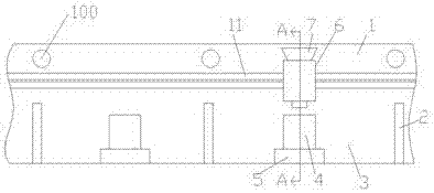
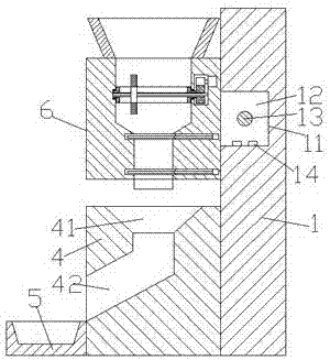
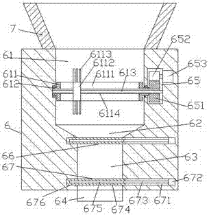
[0022] Such as Figure 1-Figure 4 As shown, a deodorizing device of the present invention includes a wall 1 provided with a straight and extended sliding guide groove 11, a sliding connecting block 12 smoothly fitted in the sliding guide groove 11 and fixed on the sliding guide groove 11. The cleaning box 6 on the front end surface of the sliding block 12, the top of the cleaning box 6 is provided with a vertical bucket 7, and the inside of the cleaning box 6 is sequentially provided with a first cleaning chamber 61, a sliding chamber 62 and a second cleaning chamber 63 , the cleaning box 6 on the rear side of the first cleaning chamber 61 is provided with a force transmission chamber 65, and the first cleaning chamber 61 is provided with a rotating tube 611 extending forward and backward, and the front and rear ends of the rotating tube 611 are Both are provided with the rotating pin shaft 612 that stretches to the front and rear sides respectively, and the extending section ...


PUM


Abstract

The invention discloses a deodorization device. The deodorization device comprises a wall provided with a sliding guide slot which is arranged in a straightly stretching mode, a sliding connection block which is smoothly arranged in the sliding guide slot in a sliding and matched mode and a cleaning box which is fixed at the end face on the front side of the sliding connection block, the top of the cleaning box is provided with an erect bucket, the inside of the cleaning box is provided with a first cleaning cavity, a sliding cavity and a second cleaning cavity from top to bottom in sequence, the portion, at the rear side of the first cleaning cavity, of the cleaning box is internally provided with a force transferring cavity, the first cleaning cavity is internally provided with a rotation pipe which is arranged to stretch front and back, both the tips on the front side and the rear side of the rotation pipe are provided with a rotational pin shaft which is arranged in a way of stretching to the front side and the rear side respectively, the portion of the rotational pin shaft which stretches to the rear side penetrates through the wall of the cleaning box and penetrates into the force transferring cavity, the tip, penetrating into the force transferring cavity, of the rotational pin shaft is provided with a first tooth disc, the middle of the inside of the rotation pipe is provided with a through hole which stretches to the front side and the rear side and penetrates through the rotational pin shaft and the first tooth disc in sequence, and the through hole is internally provided with a first stud. The deodorization device is simple in structure, is controlled automatically and is convenient to operate; meanwhile, the waste in a cleanser is reduced, and the work efficiency is improved.

Description

technical field [0001] The invention relates to the technical field of public toilet facilities, in particular to a deodorizing device. Background technique [0002] Toilets in cities are an integral part of urban infrastructure. It can facilitate people's life and meet the needs of physiological functions; it is the main place and facility for collecting, storing and initially processing urban excrement; as an urban building, the public toilet facility itself is one of the cultural landscapes, and the public toilet has become one of the windows of the image of modern urban civilization. It reflects the development level of the city's material civilization and spiritual civilization. In my country, considerable manpower and material resources are invested in the cleaning and deodorization of public toilets every year. In the existing cleaning and deodorization of public toilets, the cleaning and deodorant after mixing is used and poured into the squatting pit, and the whole...

Claims


Application Information

Patent Timeline
Patent Type & Authority Patents(China)
IPC IPC(8): E03D9/00
CPCE03D9/005
Inventor 戴美英
Owner 凤阳清碳环保科技有限公司
Why Eureka
Try Eureka