Method and device for detecting sag height of optical cable
The technology of a detection device and detection method, which is applied in the field of power communication, can solve the problems of low detection efficiency of sag height and achieve the effect of improving detection efficiency
- Summary
- Abstract
- Description
- Claims
- Application Information
AI Technical Summary
Problems solved by technology
Method used
Image

Examples
Embodiment 1
[0031] An embodiment of the present invention provides a detection device for the sag height of an optical cable.
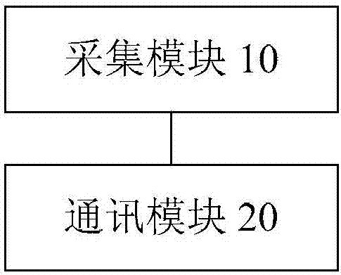
[0032] figure 1 is a schematic diagram of a detection device for the sag height of an optical cable according to an embodiment of the present invention. Such as figure 1 As shown, the detection device includes: a collection module 10 and a communication module 20 .
[0033] The acquisition module 10 is configured to acquire a target sag point of the target optical cable, and acquire a relative height of the target sag point relative to a preset plane, wherein the target sag point is a sag point on the target optical cable with the shortest height relative to the preset plane.
[0034] The target optical cable is the optical cable whose sag height is to be detected, and is erected at a preset position, for example, the target optical cable is erected on a power pole. Due to the effect of gravity, the target optical cable will form a natural sag, and the acquisi...
Embodiment 2
[0059] The embodiment of the invention also provides a method for detecting the sag height of the optical cable. It should be noted that the method for detecting the sag height of the optical cable in this embodiment can be used to implement the device for detecting the sag height of the optical cable in the above embodiment.
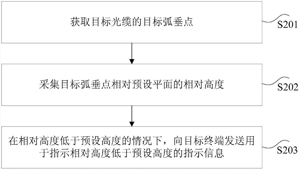
[0060] figure 2 It is a flowchart of a method for detecting the sag height of an optical cable according to an embodiment of the present invention. Such as figure 2 As shown, the detection method of the sag height of the optical cable comprises the following steps:
[0061] Step S201, acquiring the target sag point of the target optical cable.
[0062] In the technical solution provided in step S201 of the present invention, the target sag point of the target optical cable is obtained, wherein the target sag point is the sag point on the target optical cable with the shortest height relative to the preset plane.
[0063] The target optical cable i...
Embodiment 3
[0081] The technical solutions of the present invention will be described below in conjunction with preferred embodiments.
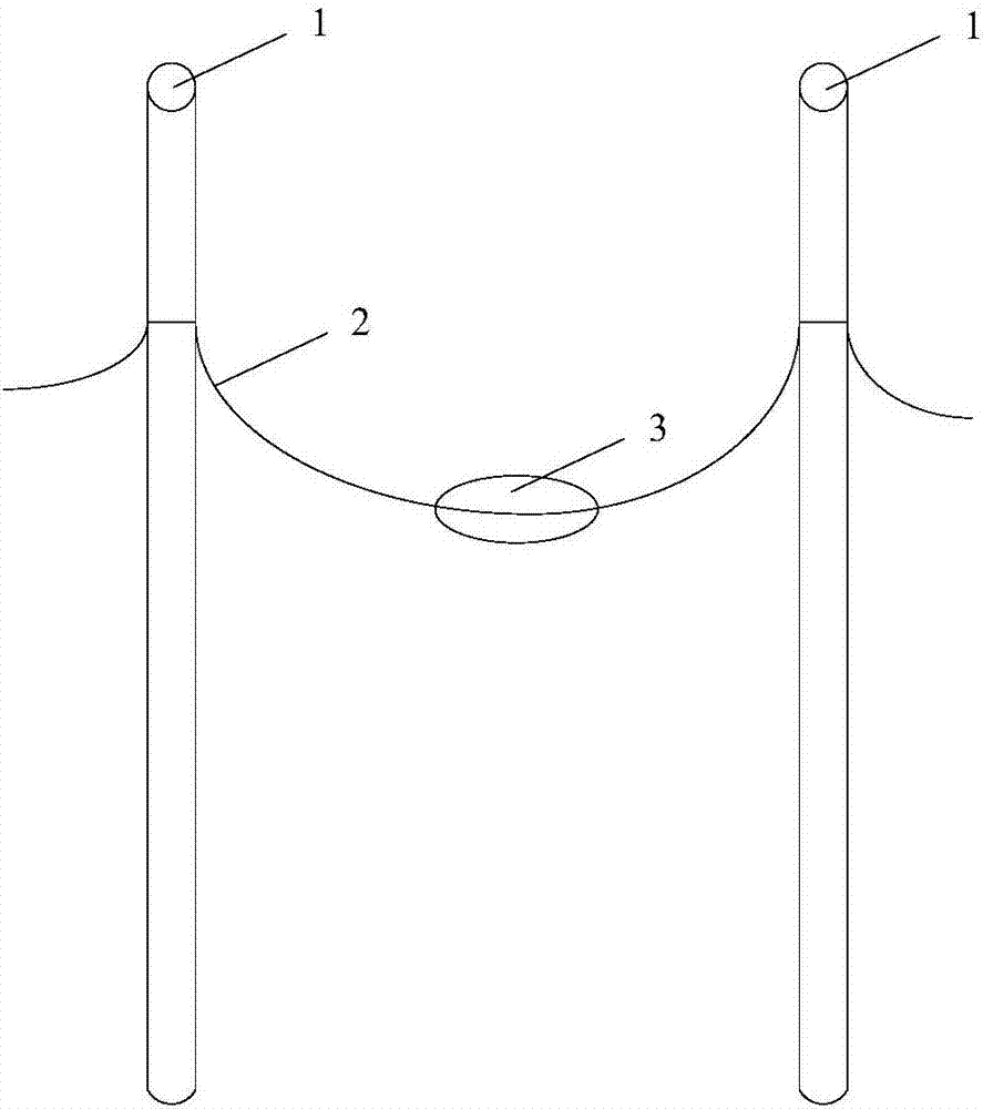
[0082] The detection device for the sag height of the optical cable in this embodiment is a small line fixing device, which can be installed on the ADSS optical cable or OPGW optical cable line, and the modular circuit design is carried out in strict accordance with industrial standards, and the appearance adopts a columnar design. It is sealed to meet the dustproof and waterproof standards, and can be manually snare at the lowest point of the cable sag. Among them, the upper part of the detection device for the sag height of the optical cable is covered with a photovoltaic silicon chip, which is connected with the internal battery to provide internal power supply for the operation of the equipment. The height of the lowest sag point relative to the ground can reach centimeter level accuracy. The interior of the detection device for the sag height of th...
PUM
 Abstract
Description
Claims
Application Information
 - R&D
- Intellectual Property
- Life Sciences
- Materials
- Tech Scout
- Unparalleled Data Quality
- Higher Quality Content
- 60% Fewer Hallucinations
Browse by: Latest US Patents, China's latest patents, Technical Efficacy Thesaurus, Application Domain, Technology Topic, Popular Technical Reports.
© 2025 PatSnap. All rights reserved.Legal|Privacy policy|Modern Slavery Act Transparency Statement|Sitemap|About US| Contact US: help@patsnap.com