TOA estimation circuit based on digital delay circuit
A digital delay and circuit technology, applied in the electronic field, can solve the problems of not being popularized in a large area and low precision
- Summary
- Abstract
- Description
- Claims
- Application Information
AI Technical Summary
Problems solved by technology
Method used
Image
Examples
Embodiment Construction
[0021] The present invention will be described in further detail below with reference to the accompanying drawings.
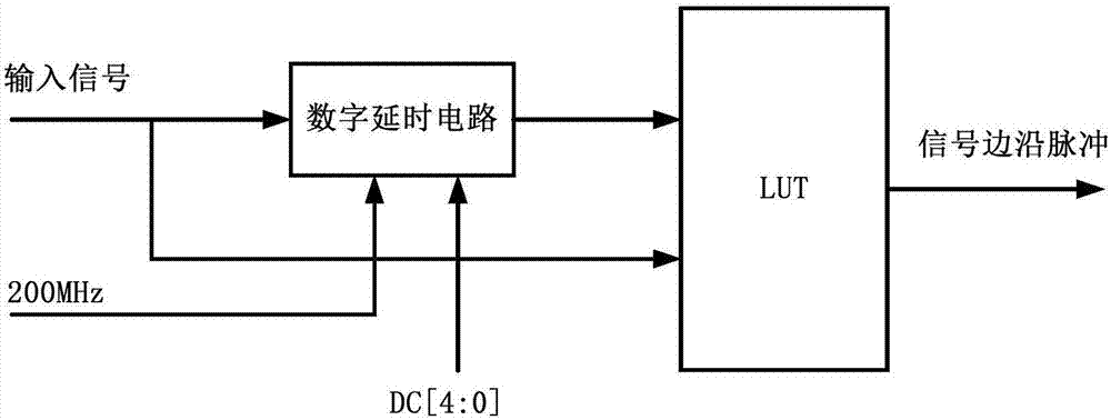
[0022] A kind of TOA estimation circuit based on digital delay circuit of the present invention, as figure 1 As shown, the circuit is composed of four modules: signal edge generation module, synchronous matching pulse generation module, time matching module and time generation module. The specific circuit diagram of the four modules is as follows: Figure 2-5 shown.
[0023] exist figure 2 In the time signal edge generation module shown, the input signal to be tested is divided into two channels, one of which enters the digital delay circuit. The delay value of the digital delay circuit can be determined by the number of cascaded basic delay units. The specific structure of the digital delay circuit See Image 6 . The other channel is directly input to the LUT unit, and the signal delayed by the digital delay circuit also enters the LUT unit; at the same ...
PUM
 Abstract
Description
Claims
Application Information
 - R&D
- Intellectual Property
- Life Sciences
- Materials
- Tech Scout
- Unparalleled Data Quality
- Higher Quality Content
- 60% Fewer Hallucinations
Browse by: Latest US Patents, China's latest patents, Technical Efficacy Thesaurus, Application Domain, Technology Topic, Popular Technical Reports.
© 2025 PatSnap. All rights reserved.Legal|Privacy policy|Modern Slavery Act Transparency Statement|Sitemap|About US| Contact US: help@patsnap.com


