LED drive circuit having silicon controlled rectifier regulator, circuit module, and control method

A technology of LED drive and circuit module, applied in the field of power electronics, can solve the problems of incompatibility between conduction position and circuit, change of conduction angle, LED load flicker, etc., and achieve the effect of avoiding LED flicker

Active Publication Date: 2017-06-23
SILERGY SEMICON TECH (HANGZHOU) CO LTD
View PDF6 Cites 45 Cited by
  • Summary
  • Abstract
  • Description
  • Claims
  • Application Information

AI Technical Summary

Problems solved by technology

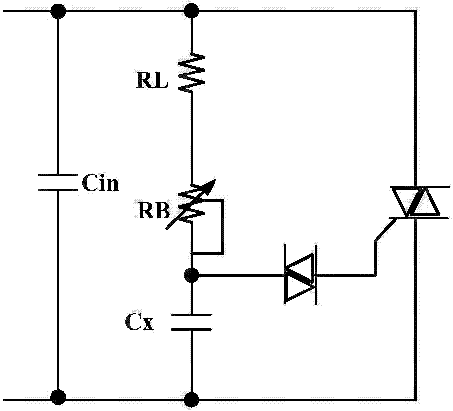
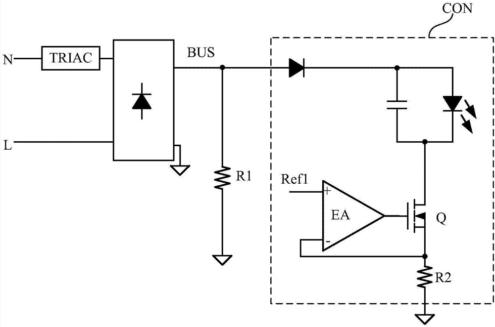
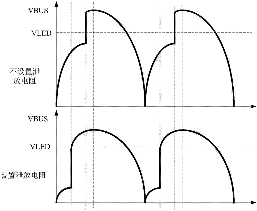
[0005] On the other hand, the thyristor dimmer will have a leakage current before it is turned on. The magnitude of the leakage current is related to the model of the thyristor dimmer and the parameter settings of the LED drive circuit. Different circuit settings and different models can TRIAC dimmers cause variations in leakage current, which in turn causes variations in conduction angle
This uncertainty will lead to the incompatibility of the conduction position and the circuit setting, resulting in the problem of flickering of the LED load

Method used


Image

  • LED drive circuit having silicon controlled rectifier regulator, circuit module, and control method
  • LED drive circuit having silicon controlled rectifier regulator, circuit module, and control method
  • LED drive circuit having silicon controlled rectifier regulator, circuit module, and control method

Examples


Embodiment Construction

[0069] The present invention is described below based on examples, but the present invention is not limited to these examples. In the following detailed description of the invention, some specific details are set forth in detail. The present invention can be fully understood by those skilled in the art without the description of these detailed parts. In order not to obscure the essence of the present invention, well-known methods, procedures, procedures, components and circuits have not been described in detail.

[0070] Additionally, those of ordinary skill in the art will appreciate that the drawings provided herein are for illustrative purposes and are not necessarily drawn to scale.

[0071] Meanwhile, it should be understood that in the following description, "circuit" refers to a conductive loop formed by at least one element or sub-circuit through electrical connection or electromagnetic connection. When an element or circuit is said to be "connected to" another eleme...


PUM


Abstract

The invention discloses an LED drive circuit having a silicon controlled rectifier regulator, a circuit module, and a control method. Before conduction of a silicon controlled rectifier regulator, a direct-current bus voltage is controlled by a bleeder circuit to change in a predetermined manner, so that a phenomenon that conduction points of the silicon controlled rectifier regulators are affected because of inconformity of leakage currents due to different types of the silicon controlled rectifier regulators and different circuit setting and thus a problem of LED scintillation can be solved. Meanwhile, with control of the direct-current bus voltage, the voltage of the silicon controlled rectifier regulator after conduction can be affected, so that the voltage of the conduction point can be set flexibly based on needs.

Description

technical field [0001] The invention relates to power electronics technology, in particular to an LED driving circuit with a thyristor dimmer, a circuit module and a control method. Background technique [0002] Thyristor dimming is a commonly used dimming method at present. The thyristor dimmer adopts the phase control method to realize dimming, that is, the conduction of the thyristor dimmer is controlled in every half cycle of the sine wave, and the same conduction phase angle is obtained. By adjusting the chopping phase of the thyristor dimmer, the conduction phase angle can be changed to realize dimming. [0003] SCR dimmers are usually used to dim incandescent lamps. With the popularity of LED light sources, more and more LED drive circuits use SCR dimmers as dimming means. [0004] In the prior art, TRIAC dimmers are usually used in combination with a linear constant current control scheme. The linear constant current control scheme adjusts the current flowing thro...

Claims


Application Information

Patent Timeline
Patent Type & Authority Applications(China)
IPC IPC(8): H05B33/08H05B44/00
CPCH05B45/44H05B45/10H05B45/3725H05B45/3575
Inventor 黄秋凯王建新陈惠强
Owner SILERGY SEMICON TECH (HANGZHOU) CO LTD
Why Eureka
Try Eureka