Clamp used for milling machine

A fixture and milling machine technology, applied in the field of milling machines, can solve problems such as poor clamping effect and difficult adjustment, and achieve the effect of simple structure, convenient use and good fastening effect

Inactive Publication Date: 2017-06-27
天津顺鑫福泰机械加工有限公司
View PDF0 Cites 3 Cited by
  • Summary
  • Abstract
  • Description
  • Claims
  • Application Information

AI Technical Summary

Problems solved by technology

[0004] The object of the present invention is to provide a clamp for milling machine, aiming to solve the problem of poor clamping effect and difficult adjustment of the milling clamp in the prior art

Method used


Image

  • Clamp used for milling machine
  • Clamp used for milling machine

Examples


Embodiment Construction

[0014] The invention provides a clamp for a milling machine, which has the advantages of simple structure, convenient use, wide clamping range and good fastening effect.

[0015] The technical solutions in the embodiments of the present invention will be described clearly and in detail below in conjunction with the accompanying drawings in the embodiments of the present invention. Obviously, the described embodiments are only part of the embodiments of the present invention, not all of them. Based on the embodiments of the present invention, all other embodiments obtained by persons of ordinary skill in the art without making creative efforts belong to the protection scope of the present invention.

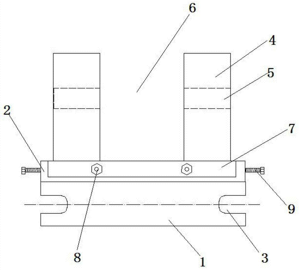
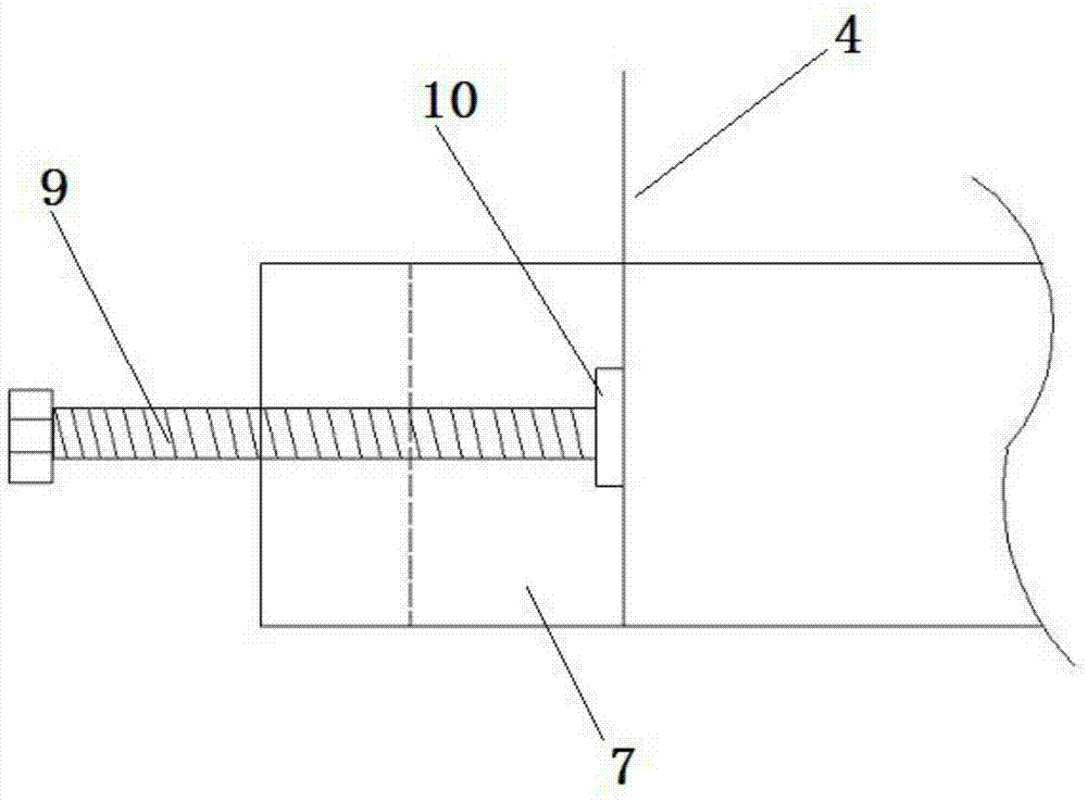
[0016] Such as figure 1 The shown clamp for a milling machine includes a fixed frame 1, a stable seat 2, a long hole 3, a clamping plate 4, a screw hole 5, a variable concave groove 6, a chute 7 and a set screw 8, and the fixed The upper end of the frame 1 is provided with a stab...


PUM


Abstract

The invention discloses a fixture for a milling machine, which comprises a fixed frame, a stable seat, a long hole, a clamping plate, a screw hole, a variable concave groove, a chute and a set screw. The upper end of the fixed frame is provided with a stable seat. The stable seat is provided with a chute, and the chute is provided with symmetrically arranged clamping plates, and the clamping plate is provided with screw holes, and the two clamping plates can slide in the chute, The two clamping plates and the chute form a variable concave groove, the side of the chute is provided with a set screw, and the set screw is used to fix the position of the clamping plate in the chute , The two sides of the fixing frame are provided with long holes. The invention has the advantages of simple structure, convenient use, wide clamping range and good fastening effect.

Description

technical field [0001] The invention relates to the technical field of milling machines, and more specifically, relates to a fixture for a milling machine. Background technique [0002] Existing gantry milling machines generally have two ways to clamp the test plate, one is to use a screw to press the plate, and the other is to use a bench vise to clamp. These two methods take a long time to align, are difficult to press, and the workpiece is prone to movement during processing, and the adjustment effect is poor, and the processing quality is poor. [0003] Therefore, due to the above-mentioned technical defects in the prior art, it is a technical problem to be solved urgently by those skilled in the art. Contents of the invention [0004] The object of the present invention is to provide a clamp for milling machine, aiming at solving the problems of poor clamping effect and difficult adjustment of the milling clamp in the prior art. [0005] To achieve the above object,...

Claims


Application Information

Patent Timeline
Patent Type & Authority Applications(China)
IPC IPC(8): B23Q3/06
CPCB23Q3/06
Inventor 刘立军
Owner 天津顺鑫福泰机械加工有限公司
Why Eureka
Try Eureka