Tank containers and their end frames

A tank container and end frame technology, which is applied in packaging, transportation and packaging, large containers, etc., can solve the problems that the tank body and the end frame cannot be welded and connected, so as to avoid deformation, improve the performance of anti-longitudinal impact load, and manufacture simple effect

Active Publication Date: 2021-04-23
NANTONG CIMC TANK EQUIP CO LTD
View PDF6 Cites 0 Cited by
  • Summary
  • Abstract
  • Description
  • Claims
  • Application Information

AI Technical Summary

Problems solved by technology

[0004] The purpose of the present invention is to provide a tank container and its end frame, which solves the problems that the tank body and the end frame cannot be welded and connected in the prior art.

Method used


Image

  • Tank containers and their end frames
  • Tank containers and their end frames
  • Tank containers and their end frames

Examples


Embodiment 1

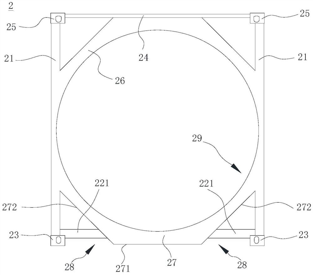
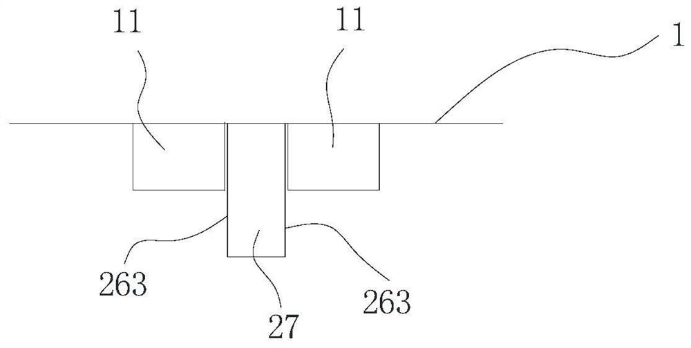
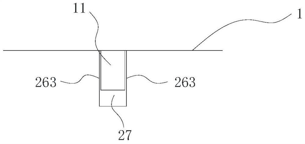
[0038] refer to Figure 1 to Figure 2B , the tank container in this embodiment includes a tank body 1 and end frames 2 arranged near both ends of the tank body, and the end frames 2 are used to support both ends of the tank body 1 . The positions of the bottoms at both ends of the tank body 1 are fixed or integrally formed with a plurality of protrusions 11 .

[0039] It should be noted that the materials of the tank body 1 and the end frame 2 in the present invention are different, and cannot be connected by welding according to conventional methods.

[0040] The end frame 2 includes: two uprights 21, an upper end beam 24 connected between the upper ends of the two uprights 21, an upper saddle 26 and a lower saddle 27, and the bottom and top ends of the uprights 21 are respectively fixed with top corner fittings 25 and bottom corner fittings 23. The top surface of the top corner piece 25 is provided with a hoisting hole (not shown in the figure), and the bottom surface of th...

Embodiment 2

[0058] refer to Figure 5 The difference between the end frame 2 in this embodiment and the end frame 2 in Embodiment 1 lies in the structure of the two support rods 221 . The two support rods 221 are connected between the upright post 21 and the lower saddle 27 and are inclined upward relative to the horizontal plane. The lower part of the end frame 2, that is, each support rod 221 and the outer side wall 272 of the lower saddle 27 adjacent to it form an avoidance groove 28a, and the avoidance groove 28a is larger in size than the avoidance groove 28 of the above-mentioned embodiment, further This reduces the chance of the support rod 221 being damaged by impact during the operation of the tank container, and reduces the use and maintenance cost of the tank container.

[0059] In actual use, the two support rods 221 can also be inclined downward relative to the horizontal plane and connected between the upright post 21 and the lower saddle 27. 27 height at one end of the co...

Embodiment 3

[0061] refer to Figure 6 The difference between the end frame 2 in this embodiment and the end frame 2 in Embodiment 1 lies in the structures of the columns 21 , the top corner pieces 25 and the bottom corner pieces 23 .

[0062] The positions near the top and the bottom of the two columns 21 of this embodiment are all deflected inwardly along the opposite direction, so that the distance between the tops of the two columns 21 and the distance between the bottoms are smaller than the distance between the middle parts of the two columns 21; 25 and bottom corner piece 23 are ISO standard parts. The structure of the column 21 makes the distance between the hoisting holes of the top corner fittings 25 installed at the tops of the two columns 21 and the distance between the fastening holes of the bottom corner fittings 23 installed at the bottoms of the two columns 21 conform to the distance of the ISO standard sling, omitting The refitting of the top corner piece 25 and the botto...


PUM


Abstract

The present invention proposes a tank container and its end frame. The end frame includes: two uprights, a lower saddle, a bottom corner piece arranged at the bottom of the two uprights, and a top corner piece arranged at the top of the two uprights. The top surface of the top corner piece is provided with a hoisting hole, and the bottom surface of the bottom corner piece is provided with a bolting hole; the lower saddle is located between the two columns and the two ends of the lower saddle are fixed or integrally formed on the The middle area of ​​the two columns is lower, and the lower saddle is formed with a concave arc bearing surface for supporting the bottom wall of the tank; the two columns and / or the side facing the lower saddle are in contact with the Supporting pieces are connected between the lower saddles. The end frame of the tank container of the present invention solves the problem that the tank body and the end frame can still be effectively connected because the tank body and the end frame cannot be connected by welding, so that the tank container can withstand transportation, lifting, stacking, etc. The loads of various operating conditions ensure the realization of functions.

Description

technical field [0001] The invention relates to a tank container, in particular to a frame structure of a frame type tank container. Background technique [0002] Tank containers, also known as tank containers, are a common means of transportation in the modern logistics industry. According to the structure of the outer frame of the tank, tank containers usually include frame tank containers. For frame tank containers, the tank body and the frame are the two basic structures of the tank container, and the connection structure between them is very important, which is related to the use safety of the entire container product. [0003] In the prior art, the tank body and the frame are generally made of metal, and often steel, and the two are mainly connected by a welding process, so that the frame and the tank body are connected into an integral structure, so that the tank container can withstand transportation, lifting, stacking, etc. code and other working conditions to ensu...

Claims


Application Information

Patent Timeline
Patent Type & Authority Patents(China)
IPC IPC(8): B65D90/20
CPCB65D90/20
Inventor 肖卫沈骏许愿梁勋南
Owner NANTONG CIMC TANK EQUIP CO LTD
Why Eureka
Try Eureka