Barrel plating production line

A production line and barrel plating technology, applied in mechanical conveyors, electrolytic components, electrolytic processes, etc., to achieve the effects of improving electroplating efficiency, improving electroplating quality and efficiency, and increasing output

Active Publication Date: 2017-06-27
KUNSHAN DONGWEI MACHINERY CO LTD
View PDF8 Cites 8 Cited by
  • Summary
  • Abstract
  • Description
  • Claims
  • Application Information

AI Technical Summary

Problems solved by technology

[0005] Therefore, the technical problem to be solved in the present invention is to overcome the problem that the prior art barrel plating production line can only carry out multi-stage processes sequentially, and cannot carry out other processes across one or more processes

Method used


Image

  • Barrel plating production line
  • Barrel plating production line
  • Barrel plating production line

Examples


Embodiment 1

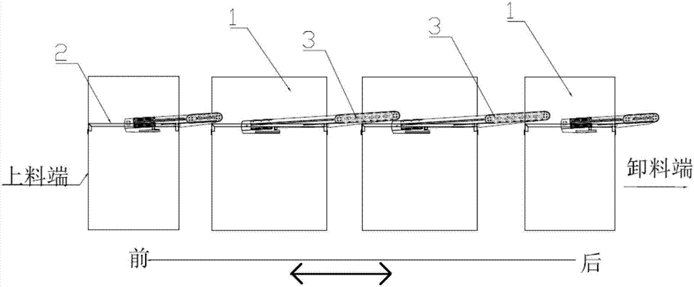
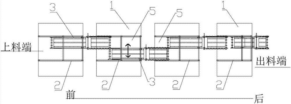
[0073] This embodiment provides a barrel plating production line, such as Figure 1 to Figure 11As shown, four barrel plating devices 1 arranged in sequence are included. For the convenience of subsequent description, the four barrel plating devices 1 are respectively named as the first barrel plating device 1, the second barrel plating device 1, and the third barrel plating device from front to back. Device 1 and the fourth barrel plating device 1, if the corresponding processes of the four barrel plating devices 1 are water washing process, anode electrolysis process, galvanizing process and passivation process, along the length direction of the arrangement of the four barrel plating devices 1, each The two ends of a barrel plating device 1 have a feed port and a discharge port respectively; two adjacent barrel plating devices 1 are slidably provided with a conveying mechanism 3 on the adjacent end faces, and one end of the conveying mechanism 3 is positioned at the front. T...

Embodiment 2

[0103] This embodiment provides a barrel plating production line, and the only difference from Embodiment 1 is that the structure of the barrel plating barrel is different. This embodiment provides a barrel plating barrel with a special structure, such as Figure 12 to Figure 24 As shown, the barrel coating barrel 10 includes a hollow barrel body, the hollow barrel body has a first section 1011, a second section 1012 and a third section 1013 along the axial direction, and the first section 1011 and the third section 1013 are located at the end of the second section 1012 On both sides; the inside of the first section 1011 is provided with a plurality of scooping parts 102 along the circumferential direction, and the second section 1012 is provided with a dialing part 103 corresponding to the scooping parts 102 along the circumferential inner wall, and the dialing part 103 The inner end of the dial extends to the side wall of the corresponding scoop member 102, and the outer end ...


PUM


Abstract

The invention discloses a barrel plating production line. The barrel plating production line comprises multiple barrel plating devices arranged in sequence; in the arrangement length direction of all the barrel plating devices, feed ports and discharge ports are respectively formed in the two end surfaces of all the barrel plating devices; conveying mechanisms are slidingly arranged on the adjacent end surfaces of two adjacent barrel plating devices; one ends of the conveying mechanisms extend into the barrel plating devices by the discharge ports of the barrel plating devices on the front sides, and the other ends of the conveying mechanisms extend into the barrel plating devices by the feed ports of the barrel plating devices on the back sides; connecting positions for enabling two adjacent ends to be positioned in overlapped areas and separation positions for enabling two adjacent ends to be positioned in staggered areas are vertically arranged at any one adjacent ends or two adjacent ends in at least one set of two adjacent conveying mechanisms; and any one adjacent ends or two adjacent ends in two adjacent conveying mechanisms move between the connecting positions and the separation positions to form the overlapped or staggered areas, so that plated workpieces are selectively input in the barrel plating devices for treatment by needed procedures according to the demands.

Description

technical field [0001] The invention relates to the technical field of electroplating of metal parts, in particular to a barrel plating production line. Background technique [0002] Barrel plating is drum electroplating, which is to place a certain number of small parts in a special drum, and deposit various metal or alloy coatings on the surface of the parts in a rolling state in an indirect conductive manner to achieve surface protection, decoration and various functions. An electroplating processing method for permanent purpose. [0003] With the continuous automation of electroplating equipment, it is necessary to continuously perform multi-stage barrel plating processes on the workpiece to be plated, such as chemical oiling, water washing, pickling, anodic electrolysis, pre-dipping, galvanizing and other processes. To carry out multi-stage or multiple processes, it is necessary to set up multiple barrel plating barrels. For example, Chinese patent document CN10619197...

Claims


Application Information

Patent Timeline
Patent Type & Authority Applications(China)
IPC IPC(8): B65G37/00B65G41/00C25D17/16
CPCC25D17/16B65G37/00B65G41/003
Inventor 张军
Owner KUNSHAN DONGWEI MACHINERY CO LTD
Why Eureka
Try Eureka