Oil well pumping pipe capable of automatically removing sand

An oil pumping pipe and oil well technology, which is applied in the field of sandstone oil reservoir mining machinery and equipment, can solve the problems of affecting the sand control effect, producing fine sand and sand, increasing costs, etc. The effect of adsorption accumulation

Active Publication Date: 2017-06-27
OIL & GAS SURVEY CGS
View PDF8 Cites 0 Cited by
  • Summary
  • Abstract
  • Description
  • Claims
  • Application Information

AI Technical Summary

Problems solved by technology

For the gravel filling method, it uses gravel with different particle sizes to filter the sand step by step, which is complex and costly, and improper gravel particle size will even affect the production capacity
For the method of running the sand control casing, the sand control casing separates the wellbore and the formation, and the sand is blocked outside. Although the process is simple, the common sand control casing does not have the function of self-cleaning, and the casing is easy to be gradually worn and affected by the accumulation of fine sand. Sand control effect, short service life, need to be replaced frequently, resulting in longer operation period, higher cost, and even affect the production of oil wells, it can only prevent the production of formation sand, but cannot prevent the formation sand from entering the wellbore
Moreover, the existing sand control methods and processes are difficult to solve the problems of severe sand production and fine sand production.

Method used


Image

  • Oil well pumping pipe capable of automatically removing sand
  • Oil well pumping pipe capable of automatically removing sand
  • Oil well pumping pipe capable of automatically removing sand

Examples


Embodiment Construction

[0027] In order to make the object, technical solution and advantages of the present invention clearer, the present invention will be further described in detail below in conjunction with the accompanying drawings and embodiments. It should be understood that the specific embodiments described here are only used to explain the present invention, not to limit the present invention.

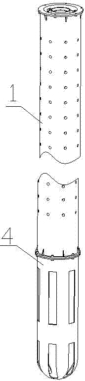
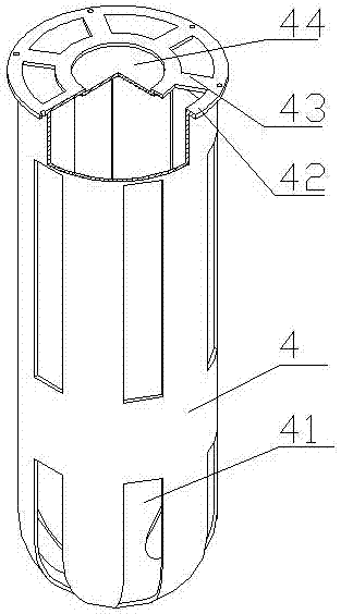
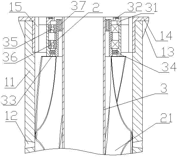
[0028] Such as Figure 1-5 As shown, the self-removing sand and gravel oil well suction pipe, the oil suction pipe is composed of a sand collection pipe 4 and several sand discharge pipes 1 butt joints from bottom to top, and the sand discharge pipe 1 includes sequentially socketed from the inside to the outside. The inner tube 3, the sand pushing rotor and the outer protective tube 11, the two ends of the outer protective tube 11 are connected to the butt end cover 14 through the rib plate 13, the top of the sand collection pipe 4 is connected to the butt end cover 42 through the rib plate, the in...


PUM


Abstract

The invention belongs to the field of mechanical equipment for sandstone reservoir exploitation, and particularly relates to an oil well pumping pipe capable of automatically removing sand. The oil pumping pipe is composed of a sand collecting pipe and multiple sand discharging pipes from bottom to top, wherein the sand collecting pipe and the sand discharging pipes are connected in a butt joint mode. Each sand discharging pipe from inside to outside comprises an inner cavity pipe, sand pushing rotors and an outer protecting pipe which are connected in a sleeved mode in sequence, wherein through holes are formed in the inner cavity pipe and the outer protecting pipe, and each sand pushing rotor is composed of a spiral screen and a sand pushing pipe arranged on the end of the spiral screen. Butt-joint end covers are arranged on both ends of each outer protecting pipe and the top of the sand collecting pipe, the tops of the sand pushing pipes are connected with annular adaptors, and the annular adaptors are connected with the outer protecting pipes and the inner cavity pipes through outer bearings and inner bearings respectively. The oil well pumping pipe is simple in structure and smart in design, on the basis of further optimizing the mechanical sand preventing effect, sand is pushed downwards by the sand pushing rotors which are driven by liquid flow in drainage, and accumulation of sand between the outer protecting pipes and the inner cavity pipes is prevented to the utmost extent.

Description

technical field [0001] The invention belongs to the field of mechanical equipment for sandstone oil reservoir exploitation, in particular to an oil well suction pipe for self-removing sandstone. Background technique [0002] my country's unconsolidated sandstone reservoirs are widely distributed and have large reserves. During the development process, it is necessary to face the problem of sand production in oil wells. It is very common in the development of this type of formation. It originates from the formation damage caused by loose and easy spalling of the reservoir or drilling and production operations. As the formation drills, the spalled formation sand enters the wellbore with the fluid, wears the pipe wall, and blocks the well. It often leads to the obstruction of oil well production, the reduction of wellbore life, and the increase of development costs. In response to formation sand, use mechanical sand control, chemical sand control, composite sand control. Amon...

Claims


Application Information

Patent Timeline
Patent Type & Authority Applications(China)
IPC IPC(8): E21B17/00E21B43/08E21B27/00
CPCE21B17/00E21B27/00E21B43/08
Inventor 李昭王劲铸辛云路葛佳金春爽白忠凯韩淼张宏达
Owner OIL & GAS SURVEY CGS
Why Eureka
Try Eureka