Method for controlling and/or regulating the hydraulic system of gearbox

A hydraulic system and transmission technology, which is applied in fluid pressure actuation system testing, transmission device control, components with teeth, etc., can solve problems that cannot be expressed, characteristic curve clusters are difficult to express and match, and achieve cost-saving effects

Active Publication Date: 2017-06-27
VOLKSWAGEN AG
View PDF8 Cites 0 Cited by
  • Summary
  • Abstract
  • Description
  • Claims
  • Application Information

AI Technical Summary

Problems solved by technology

Large clusters of characteristic curves with dependencies that are not always physically achievable are difficult to express, thus leading to t

Method used


Image

  • Method for controlling and/or regulating the hydraulic system of gearbox

Examples


Embodiment Construction

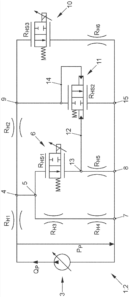
[0050] exist figure 1 A hydraulic system 1 of a motor vehicle transmission is shown very schematically in the form of a network model 2 . Motor vehicle transmissions are designed in particular as dual clutch transmissions. The dual clutch transmission has a dual clutch with two clutches K1 , K2 (not shown). Preferably, the dual clutch transmission also has a clutch K0 for coupling the electric motor to the transmission.

[0051] The hydraulic system 1 has at least one pump 3 . In particular, exactly one pump 3 is present. The pump 3 is preferably designed as an electrically driven pump 3 . In an alternative refinement, a plurality of pumps (not shown) can be present in the hydraulic system 1 , for example a main pump driven by the internal combustion engine of the motor vehicle and an electrically driven additional pump.

[0052] Pump 3 delivers the volume flow Q from the oil sump, which is not drawn in detail P . The pump 3 delivers hydraulic oil, in particular cooling...


PUM


Abstract

The invention relates to a method for controlling and/or regulating the hydraulic system (1) of gearbox wherein a pump (3) transmits hydraulic oil. A hydraulic network model (2) is used to control and/or regulate the pump (3). The hydraulic system (1) is therefore capable of efficiently controlling or regulating. The hydraulic network model (2) comprises at least one hydraulic resistor (RH1, RH2, RH3, RH4, RH5, RH6, RHS1, RHS3) wherein each volume flow of the resistors(RH1, RH2, RH3, RH4, RH5, RH6, RHS1, RHS3) is calculated. Based on the calculations, the pump (3) is controlled and regulated.

Description

technical field [0001] The invention relates to a method for controlling and / or regulating a hydraulic system of a transmission with the features stated in the preamble of patent claim 1 . The transmission is designed in particular as a hydraulically controlled motor vehicle transmission. Background technique [0002] It is known in the prior art to supply a hydraulic system with a hydraulic medium by means of a pump, wherein a pump coupled to the rotational speed of the internal combustion engine and an electric additional pump are used. The speed of the electric additional pump is adjusted or controlled according to demand. [0003] It is known from DE 11 2011 103 673 T5 to supply a hydraulic system with an accumulator with hydraulic medium from a pump mechanically coupled to the rotational speed of the internal combustion engine on the one hand and an additional pump driven electrically on the other hand. In this case, the underflow is calculated on the basis of the rot...

Claims


Application Information

Patent Timeline
IPC IPC(8): F15B19/00
CPCF15B19/007F15B2211/855F16H2061/0093F16H59/72F16H61/0021
Inventor M.福雷吉特克R.卡尔姆斯M.马赫莱夫斯基
Owner VOLKSWAGEN AG
Why Eureka
Try Eureka