LED lamp

A technology of LED lamps and housings, applied in the field of lighting, can solve problems such as difficult winding and unwinding, damage to the insulation of power supply lines, and reduced work efficiency, so as to improve the efficiency and stability of winding lines, reduce waste of mains electricity, and facilitate operation Effect

Active Publication Date: 2017-06-27
盐城明钰科技有限公司
View PDF7 Cites 3 Cited by
  • Summary
  • Abstract
  • Description
  • Claims
  • Application Information

AI Technical Summary

Problems solved by technology

[0002] In the actual construction of the construction site, due to the tight schedule or construction needs, construction needs to be carried out at night, so the lighting on the construction site has become an indispensable tool in the construction process. However, due to the long power supply connection required in the construction lighting process , making it extremely difficult to take in and out the wires, increasing the workload and reducing work efficiency. At the same time, when not in use, the power supply wires are exposed to the outside world for a long time and are vulnerable to various accidental damages, such as people trampled on, hard objects scratches, etc., resulting in power supply failures. The outer insulation of the line is damaged, resulting in a decrease in the service life of the power supply line. If it is not found in time, it is easy to induce electric shock accidents, which has a large safety hazard and brings great inconvenience to users.

Method used


Image

  • LED lamp
  • LED lamp
  • LED lamp

Examples


Embodiment Construction

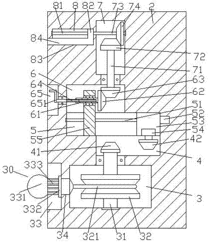
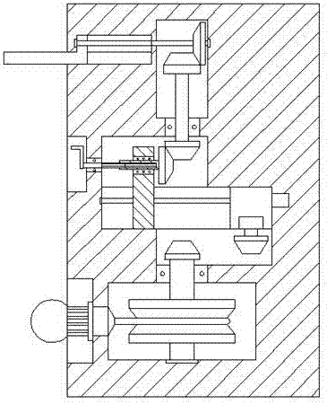
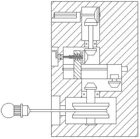
[0019] Such as Figure 1-Figure 5 As shown, an LED lamp of the present invention includes a housing 2, a sliding groove 5 is provided in the middle of the housing 2, and a second housing 2 is provided on the left side of the sliding groove 5. A tank body 6, a second tank body 4 is provided in the housing 2 on the lower right side of the sliding groove 5, and a cavity 3 is provided in the housing 2 at the bottom of the second tank body 4, A transmission cavity 7 is provided on the upper right side of the first tank body 6, a first screw rod 51 is arranged in the sliding groove 5, and the right end of the first screw rod 51 is connected with a first motor 52, The thread on the first threaded rod 51 is connected with an upwardly extending column 55 and a sliding block 53 arranged on the right side of the column 55, and the upwardly extending section of the column 55 penetrates into the first groove 6 and the inner spline shaft 61 is connected with internal rotation fit, the righ...


PUM


Abstract

The invention discloses an LED lamp which comprises a shell, wherein a sliding chute is formed in the middle part in the shell; a first trough body is arranged at a position, which is located above the left side of the sliding chute, in the shell; a second trough body is arranged at a position, which is located below the right side of the sliding chute, in the shell; an accommodating cavity is formed in a position, which is located at the bottom of the second trough body, in the shell; a transmission cavity is formed above the right side of the first trough body; a first spiral rod is arranged in the sliding chute; the right side end of the first spiral rod is connected with a first motor; the first spiral rod is in threaded fit with an upwards extending vertical column and a sliding block arranged on the right side of the vertical column; the upwards extending section of the vertical column penetrates into the first trough body, and is internally connected with an internal spline shaft in a gyration cooperation manner; a first tooth-shaped wheel is fixedly arranged at the right side end of the internal spline shaft; the internal spline shaft is internally connected with an external spline shaft in a cooperation manner; and a second tooth-shaped wheel is connected above the right side of the first tooth-shaped wheel in a hinged manner. The LED lamp is simple in structure and convenient to operate, can realize automatic take-up work, has a rain prevention function, can reduce waste of mains supply and improve the construction efficiency, is relatively low in use cost, and is suitable for being popularized and used.

Description

technical field [0001] The invention relates to the technical field of lighting, in particular to an LED lamp used for nighttime construction lighting. Background technique [0002] In the actual construction of the construction site, due to the tight schedule or construction needs, construction needs to be carried out at night, so the lighting on the construction site has become an indispensable tool in the construction process. However, due to the long power supply connection required in the construction lighting process , making it extremely difficult to take in and out the wires, increasing the workload and reducing work efficiency. At the same time, when not in use, the power supply wires are exposed to the outside world for a long time and are vulnerable to various accidental damages, such as people trampled on, hard objects scratches, etc., resulting in power supply failures. The insulation skin on the outside of the line is damaged, resulting in a decrease in the ser...

Claims


Application Information

Patent Timeline
IPC IPC(8): F21V27/00F21V31/00F21V17/10F21Y115/10
CPCF21V17/10F21V27/00F21V31/00
Inventor 叶彩
Owner 盐城明钰科技有限公司
Why Eureka
Try Eureka