Image film viewing instrument

A film viewer and imaging technology, applied in the field of medical devices, can solve problems such as inability to clearly identify and inconvenience, and achieve the effect of improving the effect and being convenient to use.

Inactive Publication Date: 2017-06-27
梁艳
View PDF0 Cites 6 Cited by
  • Summary
  • Abstract
  • Description
  • Claims
  • Application Information

AI Technical Summary

Problems solved by technology

The light source light of the currently used film viewer is evenly irradiated on the light-transmitting plate, and the local details of the image cannot be further clearly identified. Usually, it is very inconvenient to view it at another brighter light source.

Method used


Image

  • Image film viewing instrument
  • Image film viewing instrument
  • Image film viewing instrument

Examples


Embodiment Construction

[0023] The principles and features of the present invention are described below in conjunction with the accompanying drawings, and the examples given are only used to explain the present invention, and are not intended to limit the scope of the present invention.

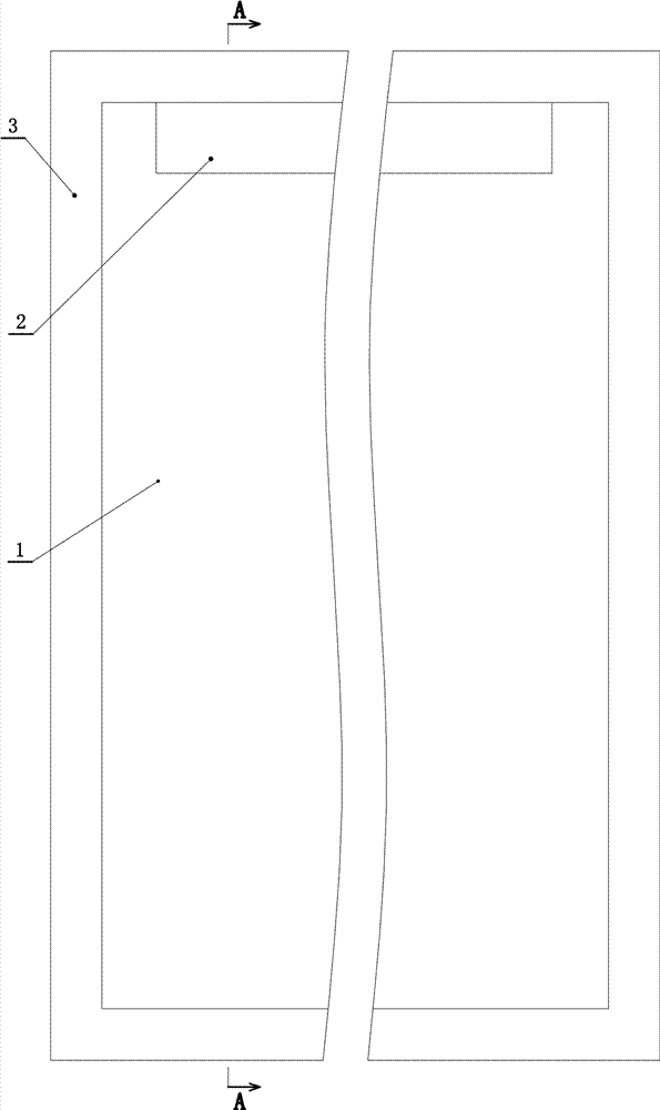
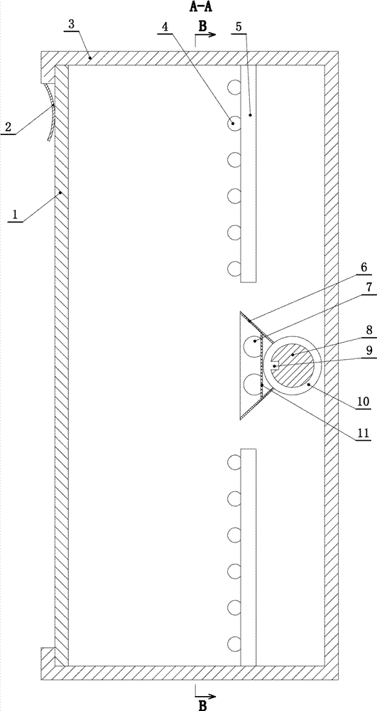
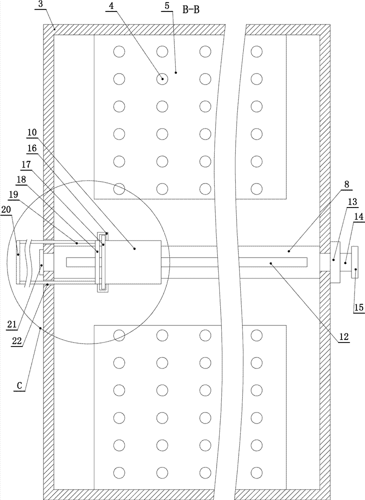
[0024] Such as Figure 1 to Figure 4 As shown, an image viewer includes a housing (3) with an opening forward, a light-transmitting plate (1) is fixedly connected to the opening end of the housing (3), and a lamp bead mounting plate ( 5), the lamp bead mounting plate (5) is fixedly installed with the light-emitting lamp bead (4) that illuminates the light-transmitting plate (1), and the upper and lower sides of the housing (3) are fixedly installed with two of the above-mentioned lamp bead mounting plates (5) , each lamp bead mounting plate (5) is respectively installed with the said light-emitting lamp bead (4), and the housing (3) between the two lamp bead mounting plates (5) is relatively rotatably connected with...


PUM


Abstract

An image viewer, in which two lamp bead mounting plates are fixedly installed up and down in the housing, and a guide shaft is connected to the housing between the two lamp bead mounting plates for relative rotation, and one end of the guide shaft is threadedly connected with a positioning nut ;The outside of the guide shaft is slid left and right to connect with a sliding sleeve, and the sliding sleeve is fixedly connected with a spotlight cover, which is located between the upper and lower lamp bead mounting plates, and a spotlight directed to the light-transmitting plate is fixedly installed in the spotlight cover, and the sliding sleeve One side is relatively rotatably connected with a push-pull ring, the guide shaft passes through the middle of the push-pull ring for relative rotation, the push-pull ring is fixedly connected with a push-pull rod, and the push-pull rod moves left and right through the side wall of the shell. The edge of the push-pull ring is fixedly connected with an anti-off rod, the anti-off rod is "U" shaped, one end of the anti-off rod is fixedly connected with the push-pull ring, the other end of the anti-off rod extends to the sliding sleeve, and the outside of the sliding sleeve is fixedly connected with The anti-off swivel ring, the edge of the anti-off swivel ring is located in the space formed by the "U"-shaped anti-off bar.

Description

technical field [0001] The invention relates to a medical device, in particular to an image viewer. Background technique [0002] Medical imaging refers to the technology and processing process of obtaining internal tissue images of the human body or a certain part of the human body in a non-invasive manner for medical treatment or medical research. The obtained image data needs to be viewed with the help of a film viewer, which is equipped with a light source The light emitted by the light source irradiates the image data through the light-transmitting plate, so that the image data presents images of internal tissues of the human body for doctors to diagnose diseases of patients. The light source of the currently used film viewer is evenly irradiated on the light-transmitting plate, and the local details of the image cannot be further clearly identified. Usually, it is very inconvenient to view it at another brighter light source. Contents of the invention [0003] The i...

Claims


Application Information

Patent Timeline
Patent Type & Authority Applications(China)
IPC IPC(8): G02B27/02
CPCG02B27/024
Inventor 王雨璇
Owner 梁艳
Why Eureka
Try Eureka