Parabolic Motion Testers and Tester Systems

A technology of parabolic movement and experimental equipment, which is applied in the direction of instruments, teaching models, educational appliances, etc., can solve problems such as experimental errors, experimental failures, and complicated operation steps, and achieve the effects of strong intuitiveness, improved teaching effect, and simple and efficient operation

Active Publication Date: 2019-04-12
李佳霖
View PDF8 Cites 0 Cited by
  • Summary
  • Abstract
  • Description
  • Claims
  • Application Information

AI Technical Summary

Problems solved by technology

[0002] Existing parabolic motion experiment devices usually include flat throwing guide rails, throwing ball switches, steel balls, ball receiving grooves, weights, bottom plates, branches and other structures; users need to carry out many preparatory steps before conducting experiments; and during experiments , it is necessary to constantly move the ball receiving groove to record the position of the steel ball at each moment, and the operation steps are complicated; and a little negligence will cause large experimental errors and even experimental failures
[0003] For the above-mentioned problem of complicated experimental operation of the parabolic motion experimental device, no effective solution has been proposed

Method used


Image

  • Parabolic Motion Testers and Tester Systems
  • Parabolic Motion Testers and Tester Systems
  • Parabolic Motion Testers and Tester Systems

Examples


Embodiment 1

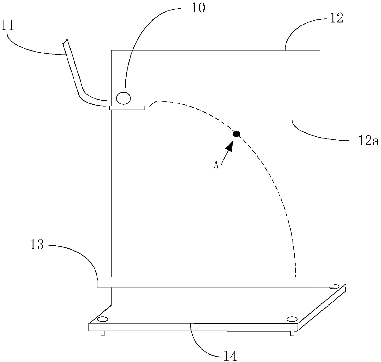
[0032] See figure 1 A schematic diagram of the structure of a parabolic motion experimental instrument shown and figure 2 A schematic diagram of the structure of the sensing circuit in the parabolic motion experiment device shown. The parabolic motion tester includes: a magnetic sphere 10, a parabolic device 11, a display board 12, a ball receiving groove 13 and a base 14. The display board 12 includes a display screen 12a, a sensor circuit (such as figure 2 (Shown) and a controller (not shown in the figure); usually, the controller can be a data processing chip such as a single-chip microcomputer, DSP, etc., integrated on the back of the base or the display board.

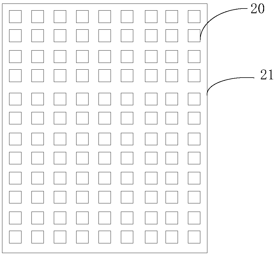
[0033] The above-mentioned display screen 12a and the sensing circuit are respectively connected to the controller; the display screen 12a and the sensing circuit are arranged overlappingly; the sensing circuit is arranged at the bottom of the display screen; that is, figure 1 In the parabolic motion tester shown, th...

Embodiment 2

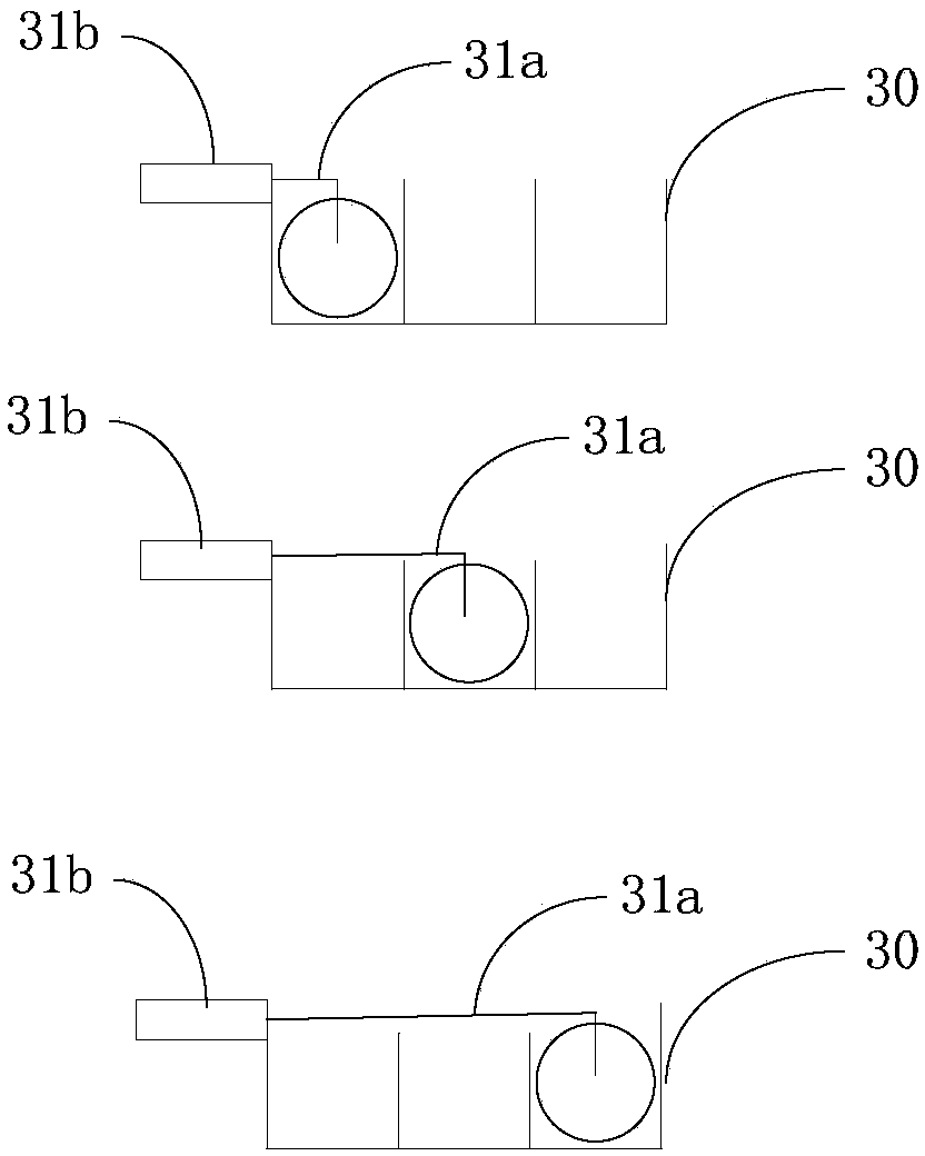
[0043] Corresponding to the parabolic motion tester provided in the first embodiment above, see image 3 In the parabolic motion tester shown, a schematic diagram of the structure of a parabolic device and Figure 4 In the shown parabolic motion tester, a top view of a parabolic device; the parabolic device is a parabolic rail 30; the number of tracks of the parabolic rail 30 is multiple ( image 3 Take three guide rails as an example); a throwing ball switch is provided on the parabolic rail 30; the throwing ball switch is slidably connected to the parabolic rail 30; the tossing ball switch is provided with a buckle part 31a and a control button 31b; the control button 31b Control the opening and closing of the buckle part 31a.

[0044] In actual implementation, since one side of the parabolic device is fixed on the display board, the control buttons of the three parabolic switches are set on the same side of the parabolic track; image 3 As shown, by arranging buckle parts of dif...

Embodiment 3

[0055] See Image 6 Shown is a schematic structural diagram of another parabolic motion tester; the parabolic motion tester is implemented on the basis of the parabolic motion tester provided in the first embodiment; specifically, the display board of the parabolic motion tester also includes a packaging frame 60; The above-mentioned display screen and the sensing circuit are arranged in the package frame 60; the base and the package frame are connected by a rotating part; the rotating part includes a bearing ( Image 6 Not shown in), the rotation angle disc 61 and the fixed part 62;

[0056] The above-mentioned bearing is arranged between the bottom side of the package frame and the base; the above-mentioned rotation angle disk 61 is arranged between the side wall of the package frame 60 and the base; the side wall of the package frame is provided with a fixing member 62; the rotation angle disk 61 is arranged There are a plurality of fixing slots 61a; the fixing component 62 is ...


PUM


Abstract

The invention provides a projectile motion experimental instrument and an experimental instrument system. The projectile motion experimental instrument comprises a magnetic ball body, a throwing device, a display panel, a ball receiving groove and a base. The display panel comprises a display screen, a sensing circuit and a controller. The sensing circuit comprises a plurality of magnetic sensors and a scanning circuit board. The plurality of magnetic sensors are arranged on the scanning circuit board at a preset interval. After the magnetic ball body is thrown out of the throwing device, the magnetic ball body conducts the parabolic movement at the front part of the display panel. During the parabolic movement, the magnetic ball body triggers the conduction of magnetic sensors at corresponding positions of the sensing circuit. The scanning circuit board sends the position signals of conducted magnetic sensors to the controller. The controller is used for sending a display signal to the display screen according to the position signals of conducted magnetic sensors, so that the display screen can display the motion track of the magnetic ball body in real time. According to the technical scheme of the invention, the projectile motion experimental operation is simple and efficient. Furthermore, the teaching effect of the projectile motion experiment is improved.

Description

Technical field [0001] The invention relates to the technical field of physical experiment devices, in particular to a parabolic motion experiment instrument and an experiment instrument system. Background technique [0002] Existing parabolic motion experiment devices usually include flat throwing rails, ball throwing switches, steel balls, ball receiving grooves, heavy hammers, bottom plates, branches and other structures; users need to perform many preparatory steps before conducting experiments; and during the experiment , It is necessary to continuously move the ball receiving groove to record the position of the steel ball at each time, and the operation steps are complicated; and a slight negligence will cause large experimental errors and even experimental failures. [0003] In view of the complex experimental operation of the aforementioned parabolic motion experimental device, no effective solution has been proposed yet. Summary of the invention [0004] In view of this, ...

Claims


Application Information

Patent Timeline
Patent Type & Authority Patents(China)
IPC IPC(8): G09B23/10
CPCG09B23/10
Inventor 李佳霖
Owner 李佳霖
Why Eureka
Try Eureka