DC electric drives and electric equipment

An electric drive and electric equipment technology, applied in the field of DC electric drives and electric equipment, can solve problems such as electric equipment failures, chopper failures, safety accidents, etc. cost effect

Active Publication Date: 2019-01-04
UNIV OF SHANGHAI FOR SCI & TECH
View PDF4 Cites 0 Cited by
  • Summary
  • Abstract
  • Description
  • Claims
  • Application Information

AI Technical Summary

Problems solved by technology

[0004] exist figure 2 In the shown DC electric drive device, the requirements for the power switch tube are extremely strict. During normal operation, the power switch tube must work below the maximum operating temperature, maximum operating current and maximum operating voltage. Once any one of the conditions is exceeded, the power switch The tube will be damaged; in addition, when the component parameters in the electronic circuit change beyond the normal operating range, overvoltage or overcurrent may be generated in the power switch tube, resulting in damage to the power switch tube and causing electrical equipment failure; in addition, With the increase of working time, the power switch tube will age, and the performance indicators such as the maximum working temperature, maximum working current and maximum working voltage will decrease accordingly, and it is very easy to cause damage to the power switch tube, which will lead to the overall failure of the chopper or short circuit. And then lead to electrical equipment failure or even safety accidents
[0005] High-power DC electric drives and electric equipment, especially low-voltage high-current DC electric drives and electric equipment, require controllers or choppers with large continuous operating currents, and related technologies and products are controlled and controlled by individual countries and companies. Monopoly, leading to high prices, and the output current value of high-performance motor controllers or choppers that can be purchased on the market is only below 1,000 amperes
In the final analysis, many reasons, such as production level, parallel current sharing technology of multiple power switch tubes, control circuits and algorithms are too complicated, have seriously restricted and affected the development of low-voltage and high-current DC electric drive devices and electric equipment.

Method used


Image

  • DC electric drives and electric equipment
  • DC electric drives and electric equipment

Examples


Embodiment Construction

[0026] The specific implementation manners of the present invention will be described below in conjunction with the accompanying drawings.

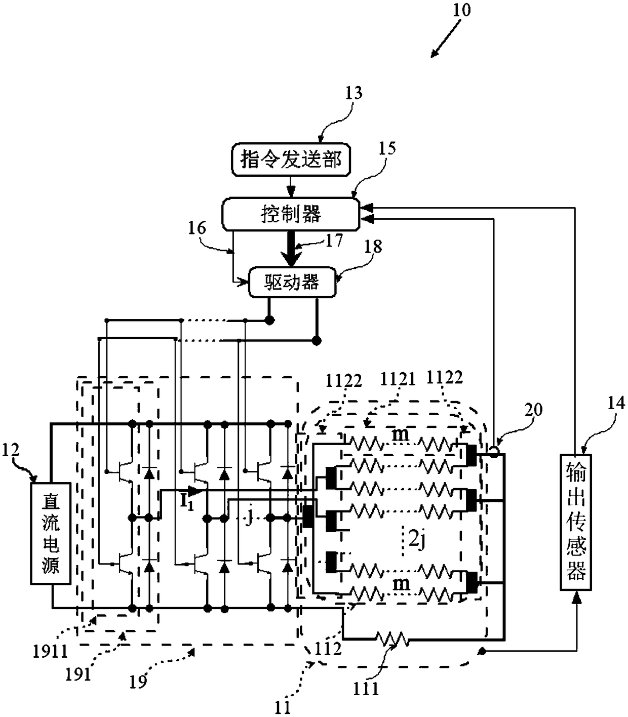
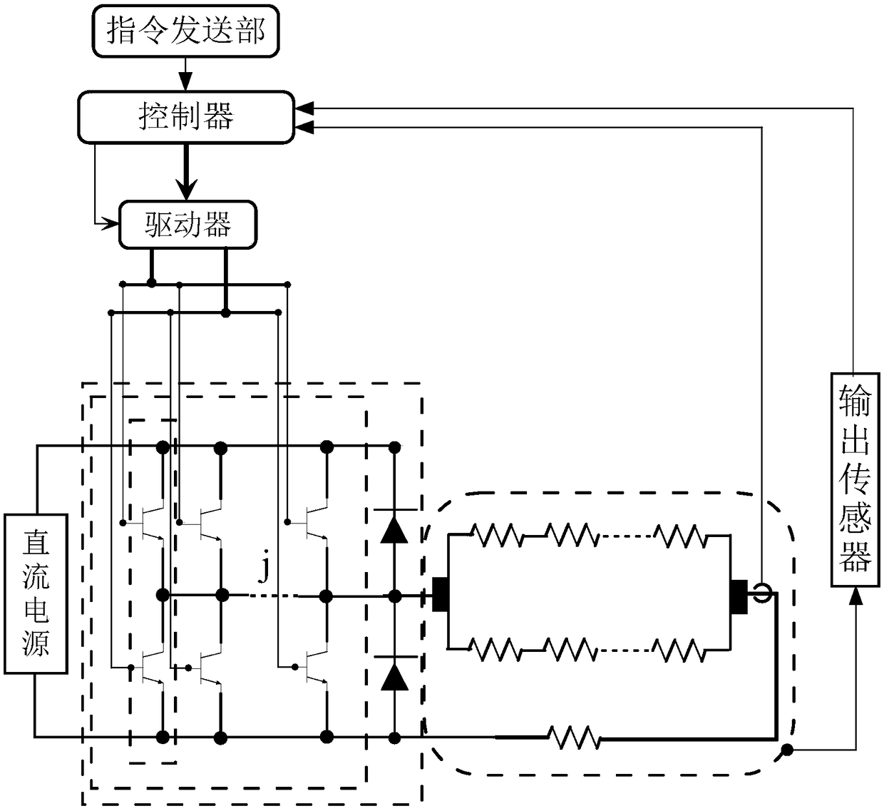
[0027] The DC electric drive device 10 is set in electric equipment such as electric tools, quadcopters, electric vehicles, electric boats, industrial electric forklifts, and electric military equipment for driving electric equipment.

[0028] figure 1 It is a schematic diagram of the circuit structure of the DC electric drive device in this embodiment.

[0029] Such as figure 1 As shown, the DC electric drive device 10 includes a DC motor 11 , a DC power supply 12 , a command sending unit 13 , an output sensor 14 , a controller 15 , a driver 18 , a chopper 19 and a current sensor 20 .

[0030] The DC motor 11 has a rated voltage and a rated current. The DC motor 11 has a main pole 111 and at least one armature 112 . In an embodiment, the DC motor has one armature 112 . The armature 112 is the rotor of the DC motor.

[0031] The m...


PUM


Abstract

The present invention provides a DC motor drive device and an electric device. The DC motor drive device is arranged in the electric device and is used for driving the electric device. The DC motor drive device comprises a DC motor, a DC power supply, a command sending part, a driver and a chopper. The DC motor is provided with 2j mutually independent armature winding branches composed of m windings, 2j * m commutator segments connected with the windings, and 2j mutually independent electric brushes connected with the chopper and in contact with the commutator segments. The chopper is a half-bridge chopper and is provided with j mutually independent chopper units. Each chopper unit contains a chopper bridge arm and a freewheeling diode in reverse and parallel connection with the chopper bridge arm, and is used for providing a linear current to a corresponding electric brush connected with the chopper unit through a current output line. Each chopper bridge arm comprises two series-connected power switch tubes. Each of the power switch tubes is in reverse and parallel connection with the freewheeling diode, wherein and m are respectively a positive integer not less than 2.

Description

technical field [0001] The invention belongs to the field of direct current motors, in particular to a direct current electric drive device and electric equipment including the direct current electric drive device. Background technique [0002] With the increase in the number of days and duration of smog in major cities, the country has become more and more strict on the exhaust emission management of fuel equipment; in addition, in a closed indoor working environment, the use of fuel equipment is prohibited; in addition, oil as an energy source It is non-renewable and will face depletion in a few decades. Therefore, electric equipment using electricity as an energy source, such as electric vehicles, electric forklifts and other electric equipment, is more and more favored by manufacturers and consumers. Not only does it have low pollution and can use the electric energy provided by renewable energy, but it also has the advantages of high energy utilization rate, simple str...

Claims


Application Information

Patent Timeline
Patent Type & Authority Patents(China)
IPC IPC(8): H02P7/285
CPCH02P7/285
Inventor 金爱娟李少龙
Owner UNIV OF SHANGHAI FOR SCI & TECH
Why Eureka
Try Eureka