Carrier frequency shift detection circuit and method

A carrier frequency offset detection circuit technology, applied in the field of carrier frequency offset detection circuit, can solve the problems of long waiting time, performance reduction of receiving circuit, etc., and achieve the effect of improving performance and reducing multiplication operations

Inactive Publication Date: 2017-06-27
MSTAR SEMICON INC
View PDF4 Cites 0 Cited by
  • Summary
  • Abstract
  • Description
  • Claims
  • Application Information

AI Technical Summary

Problems solved by technology

However, this procedure requires a long waiting time and causes a delay (latency), which reduces the performance of the receiving circuit

Method used


Image

  • Carrier frequency shift detection circuit and method
  • Carrier frequency shift detection circuit and method
  • Carrier frequency shift detection circuit and method

Examples


Embodiment Construction

[0034] The disclosure of the present invention includes a carrier frequency offset detection circuit and method. On the premise that implementation is possible, those skilled in the art can select equivalent components or steps to implement the present invention according to the disclosure in this specification, that is, the implementation of the present invention is not limited to the following embodiments.

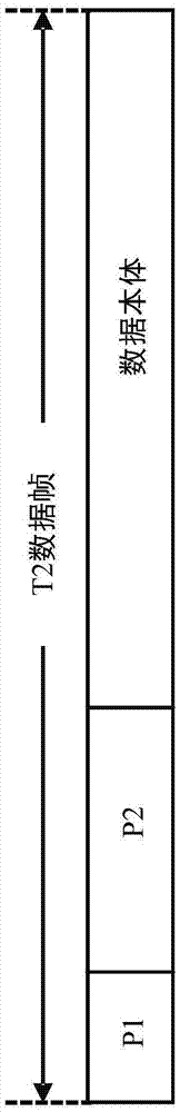
[0035] According to the definition of the DVB-T2 specification, the P1 symbol contains 1024 carriers, excluding the part of the guardband (guardband), there are 853 available carriers (corresponding to the carrier number 0~852), and 768 of them (corresponding to the carrier number 44-811) are carrier waves in use, used to transmit the encoded codeword CSS1 and the encoded codeword CSS2. The encoded codeword CSS1 and the encoded codeword CSS2 are encoding results of the codeword S1 and the codeword S2 at the transmitting end respectively. Half of the aforementioned 768 c...


PUM


Abstract

The invention discloses a carrier frequency shift detection circuit. The circuit comprises a Gray matching filter for filtering an input signal according to a group of coefficients so as to produce an output signal, wherein the group of coefficients is related with a Gray complementary sequence corresponding to the input signal; and a judgment unit for deciding a peak value the output signal, and judging a carrier frequency shift value according to the carrier serial number corresponding to the peak value.

Description

technical field [0001] The present invention relates to a carrier frequency offset detection circuit and method, in particular to a second generation digital video broadcasting (Digital Video Broadcasting over Terrestrial 2, hereinafter referred to as DVB-T2) system carrier frequency offset detection circuit and method. Background technique [0002] figure 1 It is the data frame format of the second generation digital video broadcasting system (DVB-T2). Each data frame includes P1 symbol, P2 symbol and data body. The P1 symbol contains the information of the transmitting end, such as: the fast Fourier transform mode used for modulation, the input and output mode of transmission and reception, and other information. In addition, the P1 symbol can also be used to detect the data flow, such as: the start position of the data frame, the degree of carrier frequency offset, the spectrum inversion status, etc. [0003] figure 2 It is a functional block diagram of the P1 symbol...

Claims


Application Information

Patent Timeline
Patent Type & Authority Applications(China)
IPC IPC(8): H04L27/00H04L27/148
CPCH04L27/0014H04L27/148H04L2027/0026
Inventor 珍路易斯·东史特王堃宇赖科印童泰来廖懿颖
Owner MSTAR SEMICON INC
Why Eureka
Try Eureka