Method for controlling electronic device and electronic device
A technology of electronic equipment and electronic induction, which is applied in the direction of active noise control, electrical components, transducer circuits, etc., and can solve the problem that there is no sound collection scheme for bendable electronic equipment
- Summary
- Abstract
- Description
- Claims
- Application Information
AI Technical Summary
Problems solved by technology
Method used
Image

Examples
Embodiment 1
[0023] An embodiment of the present invention provides an electronic device, and the electronic device may be a smart phone, a multimedia player, a smart bracelet, a smart watch, etc., which is not specifically limited in the present invention.
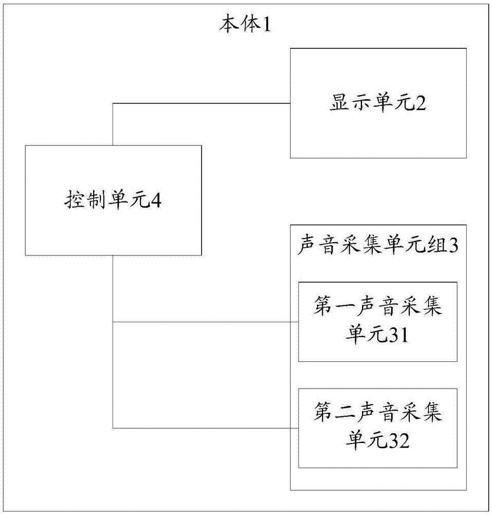
[0024] see figure 1 As shown, the electronic device includes: a main body 1; a display unit 2, which is arranged on the main body 1, and the display unit 2 has at least a first mode and a second mode; when the display unit 2 is in the first mode, all the display units on the 2 Parts are on the same plane; when the display unit 2 is in the second mode, at least two parts on the display unit 2 are not on the same plane; the sound collection unit group 3 includes at least a first sound collection unit 31 and a second sound collection unit 32 , wherein, the first sound collection unit 31 is arranged on the first end of the body 1, the second sound collection unit 32 is arranged on the second end adjacent to the first end on the body 1; th...
Embodiment 2
[0050] On the basis of the first embodiment above, when the display unit is in the first mode, in order to further achieve a better sound collection effect, noise reduction may be performed on the collected sound signals.
[0051] Then, S102 may include: when the display unit is in the first mode, controlling the first sound collection unit to work as the main collection unit, controlling the second sound collection unit to work as the auxiliary collection unit, so that the first sound collection unit cooperates with the second sound collection The unit performs noise reduction on the collected sound signal.
[0052] It should be noted that, according to the noise reduction requirements of dual sound collection units, when the display unit is in the first mode, the sound pickup direction of the first sound collection unit and the sound pickup direction of the second sound collection unit need to satisfy the first relative positional relationship , such as Figure 8A As shown ...
Embodiment 3
[0057] On the basis of the second embodiment above, when the display unit is in the second mode, in order to further achieve a better sound collection effect, noise reduction is performed on the collected sound signals, see Figure 9 As shown, the sound collection unit group 3 also includes: a third sound collection unit 33, which is arranged on the third end of the body 1 opposite to the second end, wherein the sound pickup direction of the second sound collection unit 32 and the third sound The sound pickup side of the collection unit 33 satisfies the second relative positional relationship, and the sound signal collected by the second sound collection unit does not interfere with the sound signal collected by the third sound collection unit;
[0058] Now, the control unit 4 controls the work of the third sound collection unit 32 while controlling the work of the second sound collection unit 32, and controls the first sound collection unit 31 to close, so that the second soun...
PUM
 Abstract
Description
Claims
Application Information
 - R&D
- Intellectual Property
- Life Sciences
- Materials
- Tech Scout
- Unparalleled Data Quality
- Higher Quality Content
- 60% Fewer Hallucinations
Browse by: Latest US Patents, China's latest patents, Technical Efficacy Thesaurus, Application Domain, Technology Topic, Popular Technical Reports.
© 2025 PatSnap. All rights reserved.Legal|Privacy policy|Modern Slavery Act Transparency Statement|Sitemap|About US| Contact US: help@patsnap.com