
Casing brake assembly

A braking assembly and braking element technology, which is applied in sausage making, sausage casings, sausage rolling machines, etc., can solve the problems of increasing the gap between the gathering device and the casing brake, increasing the risk, etc.

Active Publication Date: 2017-06-30
POLY CLIP SYST
View PDF8 Cites 1 Cited by
  • Summary
  • Abstract
  • Description
  • Claims
  • Application Information

AI Technical Summary

Problems solved by technology

[0006] In some cases, the casing brake has to be moved along the filling tube, especially in the direction away from the gathering device, for example to adjust the friction force applied to the casing material or to adapt the pinch-off machine to different products, between the gathering device and the casing brake The size of the gap between may undesirably increase, thereby increasing the risk of the operator's fingers reaching the gathering device

Method used


Image

  • Casing brake assembly
  • Casing brake assembly
  • Casing brake assembly

Examples


Embodiment Construction

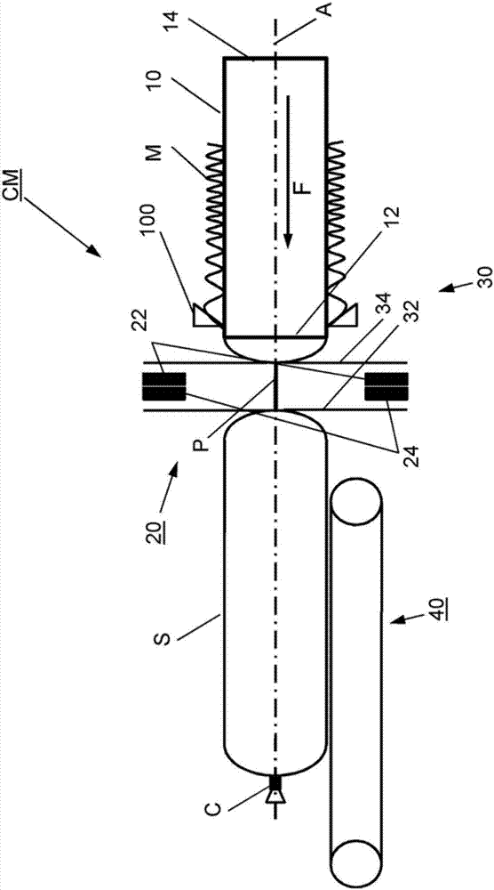
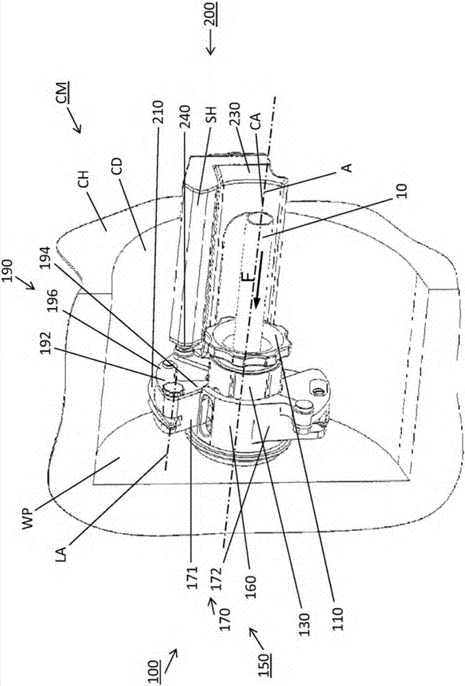
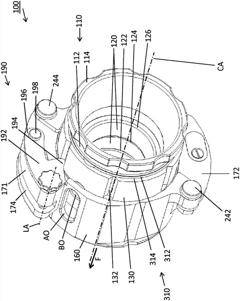
[0058] exist figure 1 The production plant or pinch-off machine CM for producing sausage-shaped products S shown in , comprises as main part a cylindrical filling tube 10 having a central axis A extending longitudinally and made of a suitable material such as stainless steel . Tubular packaging casings M made of sheet material are stored on filling tubes. The pinch-off machine CM further comprises a pinch-off device 20 and a gathering device 30 arranged downstream of the filling tube 10 for gathering the filled tubular packaging casing M and for forming a braided portion P thereon. The braided portion P is at least substantially free of filler material. A pinch-off device 20 is provided for closing the filled tubular packaging casing M by applying a closing means, such as a closing clip C, to said braided portion P.

[0059] as available from figure 1 It is further inferred that the horizontally arranged filling tube 10 has a left end 12 facing the pinch-off device 20 an...


PUM


Abstract

A casing brake assembly (100) is provided for applying a frictional force to a tubular casing being arranged on a filling tube (10) of a production apparatus (CM), which is used in the production of sausage-shaped products (S) and for limiting the movement of said tubular casing. The casing brake assembly (100) comprises tubular support means (110) for supporting at least one brake element having an at least approximately ring-shaped design. The casing brake assembly (100) further comprises a tubular bushing (130) for accommodating the tubular support means (110) and the brake element, and an attachment device (150) including a tubular accommodation portion (160) for accommodating the tubular bushing (130), and at least one attachment portion (170) configured for attaching the casing brake assembly (100) to the production apparatus (CM).

Description

technical field [0001] The invention relates to a casing brake assembly and a plant for producing sausage-shaped products comprising such a casing brake assembly. Background technique [0002] In fact, it is known, for example in the production of sausage-shaped products, that the filling material is fed by the stuffing machine via the filling tube of the pinching machine into tubular or bagged packaging casings, which are temporarily stored On the filling tube and at its front end, which is the end pointing in the feeding direction of the filling material, it is closed respectively by closing means such as closing clips, or by fusing this end. The casing of the tubular package is detached from the filling tube while being filled with the supplied pressure. In order to control the breakaway speed and ensure at least an approximately constant filling angle, at least during filling, the casing brake applies a frictional force to the tubular packaging casing while it is being ...

Claims


Application Information

Patent Timeline
Patent Type & Authority Applications(China)
IPC IPC(8): A22C13/00
CPCA22C13/0003A22C11/008A22C11/02A22C11/0245A22C11/0263A22C11/10A22C11/125A22C11/12
Inventor D.埃伯特W.尼科利
Owner POLY CLIP SYST
Learn More