Centring clamping device

A clamping device and clamping jaw technology, used in toolholder accessories, chucks, turning equipment, etc., can solve the problems of high cost, easy damage, and difficult maintenance.

Active Publication Date: 2017-06-30
SOCO MACHINERY
View PDF6 Cites 18 Cited by
  • Summary
  • Abstract
  • Description
  • Claims
  • Application Information

AI Technical Summary

Problems solved by technology

[0005] During operation, the first worm gear motor 242 and the second worm gear motor jointly drive the first large toothed disc 241 to rotate with rotating gears, and the first large toothed disc 241 drives the first and second sliders 243 with a gear set. , 244 move relatively, so that the first and second jaws 221, 222 arranged on the first and second sliders 243, 244 move relatively, and the third worm motor 252 and the fourth worm motor work together Drive the second large toothed disc 251 to rotate with the rotating teeth, and the second large toothed disc 251 drives the third and fourth sliders 253, 254 to move relatively with the gear set, so that the third and fourth sliders 253, 254 are arranged on the third and fourth sliders 253, The

Method used


Image

  • Centring clamping device
  • Centring clamping device
  • Centring clamping device

Examples


Embodiment Construction

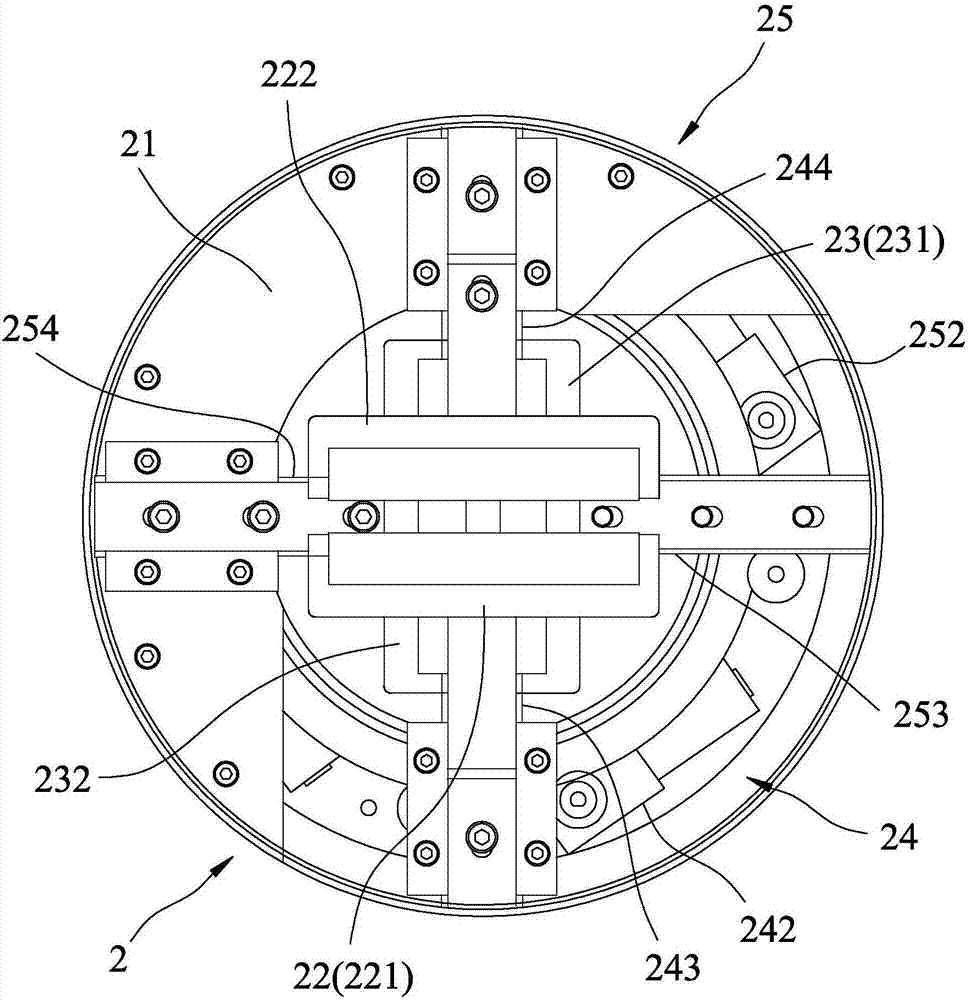
[0029] like Figures 5 to 7 As shown, one embodiment of the centering and clamping device of the present invention includes a base 4 , a clamping module 5 , and a driving module 6 .

[0030] The base 4 includes a seat body 41, and the seat body 41 is defined to have a central axis X, a first axis L1 passing orthogonally through the central axis X, and a second axis L2 passing orthogonally through the central axis X, In this embodiment, the first axis L1 and the second axis L2 are perpendicular to each other.

[0031] The clamping module 5 includes two first clamping jaw units 51 disposed opposite to the base body 41 , and two second clamping jaw units 52 disposed opposite to the base body 41 .

[0032]Each first jaw unit 51 has a first slide rail 511 disposed on the base body 41, a first slide block 512 movably disposed on the first slide rail 511, a first slide block 512 disposed on the first slide block 512 of the first jaw 513 , and a first rack 514 disposed on the first ...


PUM


Abstract

The invention discloses a centring clamping device which comprises a base, a clamping module and a driving module, wherein the base comprises a base body; the base body is provided with a central shaft; the clamping module comprises two first clamping jaw units arranged oppositely and two second clamping jaw units arranged oppositely; each of the first clamping jaw units is provided with a first clamping jaw; each of the second clamping jaw units is provided with a second clamping jaw; the driving unit comprises a first rotary disc, a second rotary disc, two first driving units and two second driving units; the first driving units drive the first rotary disc to drive the first clamping jaws of the first clamping jaw units to move in the direction of the central shaft; and the second driving units drive the second rotary disc to drive the second clamping jaws of the second clamping jaw units to move in the direction of the central shaft, so that a workpiece is clamped and fixed on the central shaft by means of the first clamping jaws and the second clamping jaws.

Description

technical field [0001] The invention relates to a workpiece clamping device, in particular to a centering clamping device. Background technique [0002] like figure 1 , 2 As shown, an existing centering and clamping device 1 includes a mandrel 11 , two turntables 12 pivotally mounted on the mandrel 11 , and four cylinders disposed on the mandrel 11 and capable of driving the turntables 12 to rotate. 13. Four movable claws 14 and four guide blocks 15 respectively connected to the movable claws 14. Each turntable 12 has two eccentric arc grooves 121 which are respectively arranged at both ends and are symmetrical to each other. The center of the circle 12 is the symmetrical point of the eccentric arc groove 121, the movable jaws 14 are arranged in a pairwise opposite manner, and one end of the guide block 15 to which the two oppositely arranged movable jaws 14 are connected The eccentric arc grooves 121 of one turntable 12 are respectively slidably connected to each other, ...

Claims


Application Information

Patent Timeline
IPC IPC(8): B23B31/12B23B31/169B23B31/30
CPCB23B31/12B23B31/16083B23B31/302
Inventor 林志远
Owner SOCO MACHINERY
Why Eureka
Try Eureka