A laser engraving machine

A laser engraving machine and laser engraving technology, applied in the field of laser engraving machines, can solve the problems of increasing the system failure rate, affecting the normal operation of the laser engraving machine, affecting the working efficiency of the laser engraving machine, etc.

Active Publication Date: 2018-11-27
河南省邮电科技有限公司
View PDF8 Cites 1 Cited by
  • Summary
  • Abstract
  • Description
  • Claims
  • Application Information

AI Technical Summary

Problems solved by technology

[0002] Laser engraving machine is a device that uses laser beams to cut or engrave non-metallic materials such as plexiglass, plastic, paper, etc. Under the control of the control system, the drive motor drives the laser engraving head to engrave or engrave the workpiece on the stage. Cutting, conventional laser engraving machines are equipped with Y-direction slides and X-direction slides that slide along the Y-direction slides. The X-direction slides are equipped with laser engraving heads that can slide along the X-direction slides. Under the control of the control system , the drive motor separately controls the sliding of the X-direction slideway and the laser engraving head to engrave the workpiece to be processed, but the simultaneous sliding of the two direction control systems increases the failure rate of the system operation, and the conventional engraving machine also fails when engraving circular patterns There are many problems; moreover, in the process of laser engraving, a large amount of dust will be generated in the casing of the laser engraving machine, and the general dust removal device can only remove part of the dust, and some dust will be removed when it touches the casing or other items. Once the dust is attached to the laser engraving head, it will not only affect the working efficiency of the laser engraving machine, but even affect the normal operation of the laser engraving machine

Method used


Image

  • A laser engraving machine
  • A laser engraving machine
  • A laser engraving machine

Examples


Embodiment Construction

[0017] The principles and features of the invention will be described in detail below in conjunction with the examples, which are only used to describe the invention and are not intended to limit the scope of the invention.

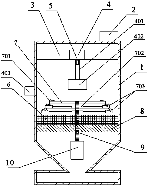
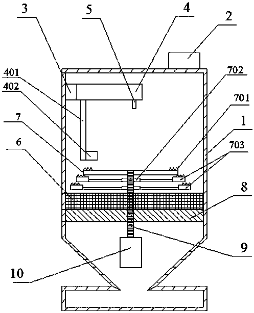
[0018] A laser engraving machine includes a casing 1 and a control device 2 arranged on the top of the casing. A working area and a dust storage area connected to the working area are arranged inside the casing. The inner wall of the working area is along the There is an X-direction slideway 3 arranged in the horizontal direction, a Y-direction slideway 4 that can slide along the X-direction slideway is arranged on the X-direction slideway, a laser engraving head 5 is arranged at the bottom of the Y-direction slideway, and a working The workbench includes a dust removal platform 6 fixed on the inner wall of the casing and a rotating platform 7 arranged above the dust removal platform. An annular blocking plate 701 coaxial with the rotating platform 7 is pr...


PUM


Abstract

The invention provides a laser engraving machine. The laser engraving machine is characterized in that a laser engraving head is fixed on a Y-direction sliding rail which can slide along an X-direction sliding rail; a workbench is arranged right below the laser engraving head, and comprises a dust removing platform and a rotating platform; the dust removing platform is fixed on the inner wall of a machine shell; the rotating platform is arranged above the dust removing platform; through the Y-direction sliding rail and the rotating platform, a to-be-machined part can be engraved with laser; meanwhile, in order to further reduce dust generated during the work of the laser engraving machine, a dust removing fan which coaxially rotates with the rotating platform is arranged below the rotating platform; and accordingly, the dust removing function can be achieved when the laser engraving machine works.

Description

technical field [0001] The invention belongs to the technical field of laser engraving, and in particular relates to a laser engraving machine. Background technique [0002] Laser engraving machine is a device that uses laser beams to cut or engrave non-metallic materials such as plexiglass, plastic, paper, etc. Under the control of the control system, the drive motor drives the laser engraving head to engrave or engrave the workpiece on the stage. Cutting, conventional laser engraving machines are equipped with Y-direction slides and X-direction slides that slide along the Y-direction slides. The X-direction slides are equipped with laser engraving heads that can slide along the X-direction slides. Under the control of the control system , the drive motor separately controls the sliding of the X-direction slideway and the laser engraving head to engrave the workpiece to be processed, but the simultaneous sliding of the two direction control systems increases the failure rat...

Claims


Application Information

Patent Timeline
Patent Type & Authority Patents(China)
IPC IPC(8): B23K26/362B23K26/402
CPCB23K26/361B23K26/402
Inventor 陈凝牛震张岩佟铭韩小敏吴俊李冠辉
Owner 河南省邮电科技有限公司
Why Eureka
Try Eureka