Novel anti-seismic support special for shield tunnel pre-buried channel

A technology for pre-embedded channels and shield tunnels, which is applied in mining installations, mining equipment, earth-moving drilling, etc., can solve problems such as difficulty in meeting the requirements of seismic specifications, difficulty in meeting lateral seismic requirements, and inability to guarantee lateral stability, etc. Achieve the effect of meeting seismic requirements, simple structure and low production cost

Pending Publication Date: 2017-06-30
CHINA RAILWAY LIUYUAN GRP CO LTD
View PDF7 Cites 2 Cited by
  • Summary
  • Abstract
  • Description
  • Claims
  • Application Information

AI Technical Summary

Problems solved by technology

Although this type of support meets the seismic requirements and has good horizontal and vertical stability, it cannot meet the engineering requirements due to the need for secondary openings
[0004] see as Figure 8 As shown, the base plate 1 of the ordinary chute bracket is directly fixed on the pre-embedded chute by the T-shaped bolt 6 and the nut 7 of the chute. There is no horizontal brace, and the lateral stability cannot be guaranteed. holes, but it is difficult to meet the requirements of seismic codes
[0005] To sum up, in the past, the ordinary chute support had no transverse braces, so it was difficult to meet the lateral seismic requirements, and the ordinary seismic support with transverse braces could not avoid secondary openings. Therefore, the underground engineering field urgently needs a A new type of anti-seismic support that meets the anti-seismic requirements and can avoid secondary openings on the shield segments

Method used


Image

  • Novel anti-seismic support special for shield tunnel pre-buried channel
  • Novel anti-seismic support special for shield tunnel pre-buried channel
  • Novel anti-seismic support special for shield tunnel pre-buried channel

Examples


Embodiment Construction

[0023] In order to more clearly illustrate the technical solutions in the embodiments of the present invention or the prior art, the following will briefly introduce the drawings that need to be used in the description of the embodiments or the prior art. Obviously, the accompanying drawings in the following description are only These are some embodiments of the present invention. For those skilled in the art, other drawings can also be obtained according to these drawings without any creative effort.

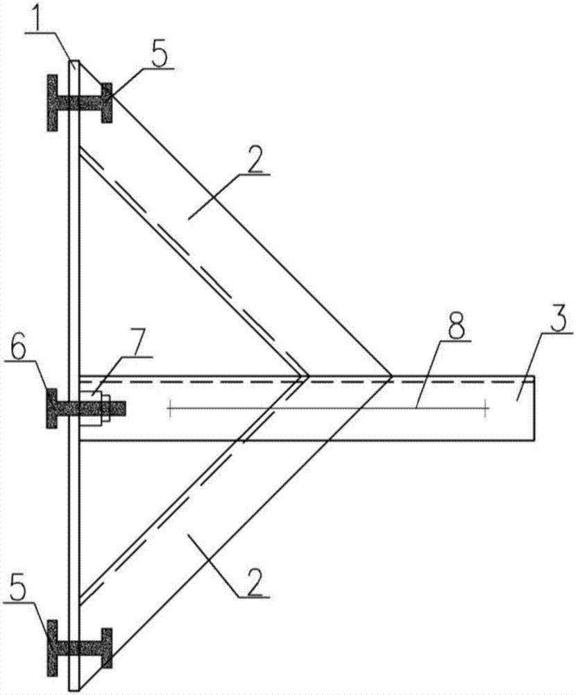
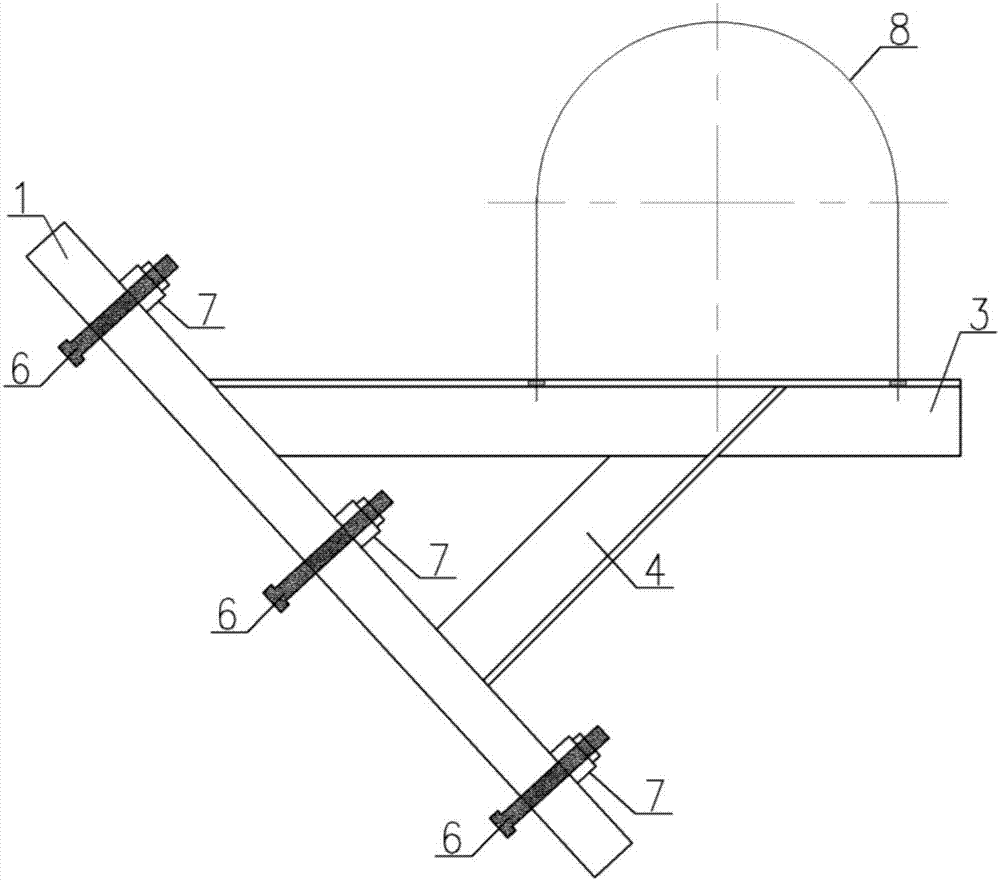
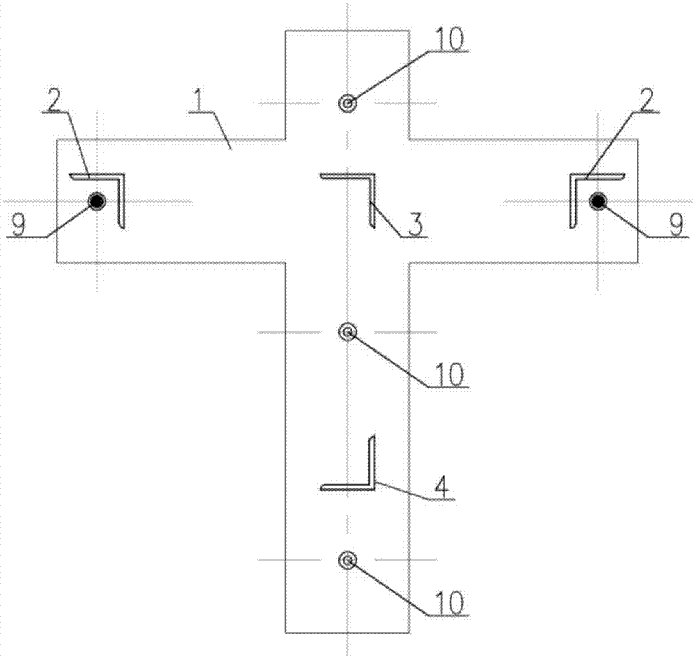
[0024] see as figure 1 —— Figure 6 As shown, this specific embodiment adopts the following technical scheme: it includes base steel plate 1, transverse brace angle steel 2, support angle steel 3, longitudinal brace angle steel 4, jacking bolt 5, chute T-bolt 6, nut 7 and Tube clamp 8; the base steel plate 1 is welded with transverse brace angle steel 2 and longitudinal brace angle steel 4, and the middle part of the base steel plate 1 is welded with support angle steel 3; th...


PUM


Abstract

The invention discloses a novel anti-seismic support special for a shield tunnel pre-buried channel and relates to the technical field of underground engineering pipeline mounting. The anti-seismic support comprises a base steel plate, transverse inclined strut angle steel, supporting angle steel, longitudinal inclined strut angle steel, pushing bolts, sliding groove T-shaped bolts, nuts and a pipe clamp. The transverse inclined strut angle steel and the longitudinal inclined strut angle steel are welded to the base steel plate; the supporting angle steel is welded in the middle of the base steel plate; the base steel plate is fixed to the pre-buried channel through the sliding groove T-shaped bolts and the nuts; the multiple pushing bolts are arranged on the base steel plate; and the pipe clamp is fixed to the supporting angle steel. According to the novel anti-seismic support special for the shield tunnel pre-buried channel, the anti-seismic requirement can be met, and secondary tapping in a shield segment can be avoided, so that the problem of pipeline anti-seismic mounting difficulty extensively existing in the underground engineering of the pre-buried channel is satisfactorily solved, and the novel anti-seismic support has the advantages of being simple in structure, reasonable in arrangement, low in manufacturing cost and the like.

Description

technical field [0001] The invention relates to the technical field of installation of underground engineering pipelines, in particular to a new anti-seismic support specially used for pre-buried channels of shield tunnels. Background technique [0002] With the development of economy and technology, in order to facilitate the mechanical and electrical installation of shield tunnels, avoid secondary opening of shield segments, and maintain the effect of fully waterproof shield tunnels, pre-buried channel technology is more and more widely used in the field of underground engineering. With the implementation of "Code for Seismic Design of Building Electromechanical Engineering" (GB50981-2014), the electromechanical system of important projects needs to be specially designed for earthquake resistance. [0003] see as Figure 7 As shown in the figure, except that the middle base steel plate 1 needs to be fixed on the pre-embedded chute with T-bolt 6 and nut 7 of the chute, the ...

Claims


Application Information

Patent Timeline
Patent Type & Authority Applications(China)
IPC IPC(8): E21F17/02
CPCE21F17/02
Inventor 吕青松贺维国李勇金若翃段悟哲田峰毕经东刘鹏宋超业周金忠全荷敏郑新定冯霞朱祝龙程士好方祖磊任靳玉王倩李晓明陈宜汉陈洋李浩陈小飞王星李明君曹灿冯巍
Owner CHINA RAILWAY LIUYUAN GRP CO LTD
Why Eureka
Try Eureka