A Power Modeling Method for Inverter Station after UHV DC Blocking

An ultra-high voltage DC, modeling method technology, applied in the field of inverter station power modeling, can solve the problem of lack of models of power change characteristics

Active Publication Date: 2019-08-06
HOHAI UNIV +2
View PDF3 Cites 0 Cited by
  • Summary
  • Abstract
  • Description
  • Claims
  • Application Information

AI Technical Summary

Problems solved by technology

[0004] Nowadays, there are few studies on the output active and reactive power of the inverter station after UHVDC blocking, and the model describing its power variation characteristics is even more lacking.

Method used


Image

  • A Power Modeling Method for Inverter Station after UHV DC Blocking
  • A Power Modeling Method for Inverter Station after UHV DC Blocking
  • A Power Modeling Method for Inverter Station after UHV DC Blocking

Examples


Embodiment Construction

[0042] The present invention will be further described below in conjunction with the accompanying drawings. The following examples are only used to illustrate the technical solution of the present invention more clearly, but not to limit the protection scope of the present invention.

[0043] A power modeling method of an inverter station suitable for UHVDC blocking of the present invention, the power includes active power and reactive power, wherein the modeling process of active power includes the following steps:

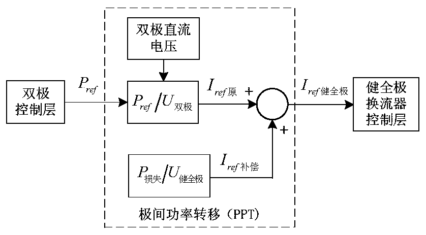
[0044] Step S11, complete the inter-pole power transfer after unipolar blocking, and calculate the current reference value I required by the sound pole ref健全极 ;

[0045] The UHV DC transmission system adopts the neutral point grounding method at both ends of the bipolar poles, and each pole adopts the wiring method of two 12-pulse converters connected in series. The two poles (positive and negative poles) operate at the same time. When there is a problem with t...


PUM


Abstract

The invention discloses a power modeling method suitable for an inverter station after ultra-high voltage direct current latching, and belongs to the field of power system modeling. According to the mechanism of polar power transfer and reactive power control after the ultra-high voltage direct current latching, an active model modeling method and a reactive model modeling method of the converter station under the condition of ultra-high voltage direct current latching are provided for the requirements of the receiving end grid side respectively, and parameter obtaining methods in models are further provided. The modeling method has correctness and accuracy, and can be used for simulation study and engineering of the actual alternating-current grid electromechanical process.

Description

technical field [0001] The present invention relates to the technical field of power system modeling, in particular to a power modeling method for inverter stations after UHV DC blocking. This model can be used to study the influence of UHV DC blocking on the receiving end and can be applied to actual AC Simulation research and engineering of power grid electromechanical process. Background technique [0002] Ultra-high voltage direct current transmission (UHVDC) has the advantages of large transmission capacity, small transmission loss, long transmission distance, etc., which helps my country to realize the optimal allocation of energy resources, so it develops very rapidly. played an important role. [0003] In daily operation, the failure of the DC transmission system converter or the failure of the DC line will cause the commutation failure of the DC system or the DC blocking. failure or even DC blocking failure. However, after it is blocked, it will have a serious imp...

Claims


Application Information

Patent Timeline
Patent Type & Authority Patents(China)
IPC IPC(8): H02J3/36
CPCH02J3/36H02J2203/20Y02E60/60
Inventor 赵健张毅明鞠平熊浩清程晓絮陈军韩敬东吴峰陈广巍代飞陈谦
Owner HOHAI UNIV
Why Eureka
Try Eureka