Method for Generating Minimum Spectrum Optical Tree for Any Multicast Service Routing with Shared Optical Path Combination

A multicast service and optical tree technology, which is applied in multiplexing system selection devices, electromagnetic network arrangements, electrical components, etc., can solve problems such as difficulty in finding available resources, isolated and discontinuous spectrum fragments, and service utilization. Achieve the effect of improving spectrum utilization, reducing bandwidth blocking rate and spectrum fragmentation

Active Publication Date: 2019-03-22
重庆信科设计有限公司
View PDF5 Cites 0 Cited by
  • Summary
  • Abstract
  • Description
  • Claims
  • Application Information

AI Technical Summary

Problems solved by technology

In the process of dynamic arrival and departure of any multicast service, and the continuous establishment and removal of optical trees, the spectrum of the path will be fragmented. These small, isolated and discontinuous spectrum fragments cannot be used by subsequent services.
When the load is heavy, it is difficult for any multicast service to find available resources through optical tree transmission, which will cause service congestion, increase the network congestion rate, and reduce network performance

Method used


Image

  • Method for Generating Minimum Spectrum Optical Tree for Any Multicast Service Routing with Shared Optical Path Combination
  • Method for Generating Minimum Spectrum Optical Tree for Any Multicast Service Routing with Shared Optical Path Combination
  • Method for Generating Minimum Spectrum Optical Tree for Any Multicast Service Routing with Shared Optical Path Combination

Examples


Embodiment

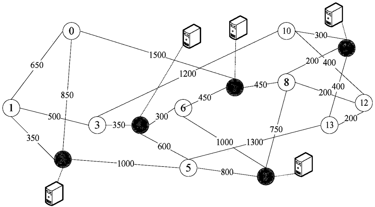
[0032] As attached figure 1 Shown is a flexible optical interconnection data center network, which is an application scenario of the present invention. The physical topology of the flexible optical interconnection data center network is G (V, E), and V represents the node set. Each node in the network has BV-WXC (Bandwidth-Variable Wavelength-Cross-Connect), which can make the signal add, drop and pair Signals are exchanged and forwarded, E represents the link set, and the maximum bandwidth capacity of any link is represented by B. There are several fixed data centers in the network to provide services for the business. Each data center has a local connection with the switching node in the network, and the switching node connected to the data center is V DC .

[0033] An arbitrary multicast request can be expressed as R(s, D c ,k,b), where the source node is s, D c ={d 1 ,d 2 ,...,d c } Is a series of candidate destination nodes, namely data centers, c is the number of data cent...


PUM


Abstract

The present invention relates to a shared optical path merging-based manycast service routing minimum spectrum optical tree generating method and belongs to the optical fiber communication technical field. The method is mainly used for the manycast service routing transmission of an elastic optical interconnection data center network. According to the method, the spectrum consumption cost value of optical three transmission is designed; a minimum spectrum optical tree generation method is put forward; based on integrated consideration on the influence of newly added trunks on the maximum length and modulation level selection of optical trees, an optical tree with the minimum spectrum consumption cost is selected to transmit services; an optical forest link sharing degree formula is designed; a link sharing degree-based optical forest merged optical tree mechanism is designed; and when some services are terminated, enough resources are released, optical forest transmission services satisfying conditions are reconfigured to the optical tree resources which are released by the terminated services, so that the optical forest transmission services can be transmitted on the optical tree resources. With the method of the invention adopted, the service bandwidth blocking rate and spectrum fragments of the elastic optical interconnection data center network can be significantly decreased, and the spectrum utilization rate of the network can be improved.

Description

Technical field [0001] The invention belongs to the technical field of optical fiber communication, and relates to a method for generating a minimum spectrum optical tree for any multicast service routing combined with shared optical paths. Background technique [0002] In recent years, with cloud computing, large-scale scientific computing (such as weather forecasting, parallel design, astrophysics and climate models), data-centric computing (high energy physics and astronomy), interactive TV and 3D games, electronic research, etc. With the rise and continuous development of data centers, the demand for bandwidth between data centers continues to increase. Cisco’s May 2013 research report pointed out: In 2018, global IP requests will exceed the 1.4ZB threshold. Global IP requests have increased by more than four times in the past five years. Will grow rapidly. So far, there are more than 500,000 data centers in the world, with an annual growth rate of 32%. With the continuous...

Claims


Application Information

Patent Timeline
Patent Type & Authority Patents(China)
IPC IPC(8): H04B10/272H04Q11/00
CPCH04B10/272H04Q11/0005H04Q11/0062H04Q2011/0047H04Q2011/0073H04Q2011/0086H04Q2011/0096
Inventor 刘焕淋杨玉明陈勇熊翠连杜君丹
Owner 重庆信科设计有限公司
Why Eureka
Try Eureka