Cutting device used for leather manufacturing

A cutting device and leather technology, applied in leather punching/punching/cutting, small raw hide/large raw hide/leather/fur processing, application, etc., can solve the problems of uneven cutting section and inconvenient use.

Active Publication Date: 2017-07-04
烟台金科自动化科技有限公司
View PDF9 Cites 9 Cited by
  • Summary
  • Abstract
  • Description
  • Claims
  • Application Information

AI Technical Summary

Problems solved by technology

[0006] In order to overcome the shortcomings of the existing cutting device for leather manufacturing, such as irregular cutting section and inconvenient use, the technical problem to be solved by the present invention is to provide a cutting device for leather manufacturing

Method used


Image

  • Cutting device used for leather manufacturing
  • Cutting device used for leather manufacturing
  • Cutting device used for leather manufacturing

Examples


Embodiment 1

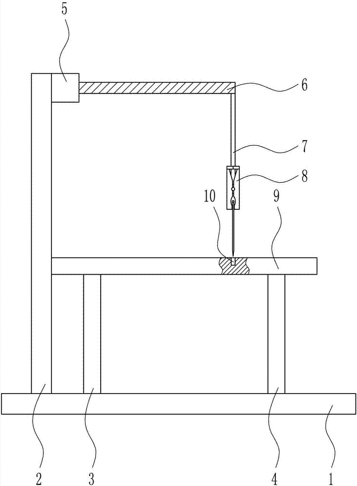
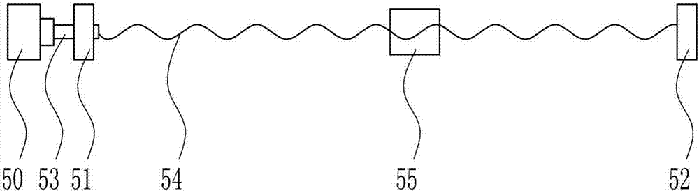
[0037] A cutting device for leather manufacture, such as Figure 1-7 As shown, it includes a base plate 1, a first support 2, a left support 3, a right support 4, a moving device 5, a second support 6, a pole 7, a cutting device 8 and a table 9, and the top of the base plate 1 is in order from left to right There is a first bracket 2, a left bracket 3 and a right bracket 4, a mobile device 5 is provided on the upper right side of the first bracket 2, a second bracket 6 is provided on the right side of the mobile device 5, and a pole is provided at the right end of the bottom of the second bracket 6 7. A cutting device 8 is provided at the lower end of the pole 7, a table 9 is provided on the top of the left bracket 3 and the right bracket 4, and a groove 10 is opened on the right side of the top of the table 9.

Embodiment 2

[0039] A cutting device for leather manufacture, such as Figure 1-7 As shown, it includes a base plate 1, a first support 2, a left support 3, a right support 4, a moving device 5, a second support 6, a pole 7, a cutting device 8 and a table 9, and the top of the base plate 1 is in order from left to right There is a first bracket 2, a left bracket 3 and a right bracket 4, a mobile device 5 is provided on the upper right side of the first bracket 2, a second bracket 6 is provided on the right side of the mobile device 5, and a pole is provided at the right end of the bottom of the second bracket 6 7. A cutting device 8 is provided at the lower end of the pole 7, a table 9 is provided on the top of the left bracket 3 and the right bracket 4, and a groove 10 is opened on the right side of the top of the table 9.

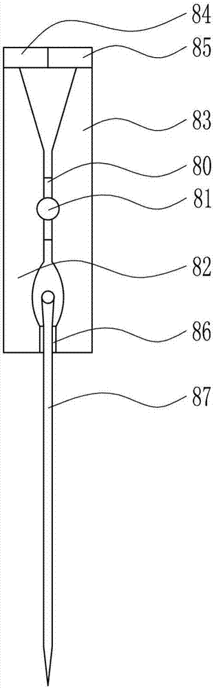
[0040] The cutting device 8 includes a first bearing seat 80, a second rotating shaft 81, a left clamping plate 82, a right clamping plate 83, a first magnet 84, an i...

Embodiment 3

[0042] A cutting device for leather manufacture, such as Figure 1-7 As shown, it includes a base plate 1, a first support 2, a left support 3, a right support 4, a moving device 5, a second support 6, a pole 7, a cutting device 8 and a table 9, and the top of the base plate 1 is in order from left to right There is a first bracket 2, a left bracket 3 and a right bracket 4, a mobile device 5 is provided on the upper right side of the first bracket 2, a second bracket 6 is provided on the right side of the mobile device 5, and a pole is provided at the right end of the bottom of the second bracket 6 7. A cutting device 8 is provided at the lower end of the pole 7, a table 9 is provided on the top of the left bracket 3 and the right bracket 4, and a groove 10 is opened on the right side of the top of the table 9.

[0043] The cutting device 8 includes a first bearing seat 80, a second rotating shaft 81, a left clamping plate 82, a right clamping plate 83, a first magnet 84, an i...


PUM


Abstract

The invention relates to a cutting device, and especially relates to a cutting device used for leather manufacturing. The technical problem to be solved is to provide a cutting device used for leather manufacturing. In order to solve the above technical problem, the invention provides the cutting device used for leather manufacturing. The device comprises a bottom board, a first support, a left support, a right support, a moving device, and a second support. The top of the bottom board is provided with the first support, the left support and the right support from left to right in sequence. The upper end of the right side of the first support is provided with the moving device. The right side of the moving device is provided with the second support. The right end of the bottom of the second support is provided with a strut. The lower end of the strut is provided with a cutting device. The top of the left support and the right support is provided with a table board. The right side of the top of the table board is provided with a groove. The cutting device achieves effects of a tidy cutting section and convenient use. The device can conveniently and rapidly change height positions of a blade, and a person does not need to hold leather by hand in cutting.

Description

technical field [0001] The invention relates to a cutting device, in particular to a cutting device for leather production. Background technique [0002] Leather is denatured and non-perishable animal skin obtained through physical and chemical processing such as depilation and tanning. Leather is composed of natural protein fibers tightly woven in three-dimensional space. There is a special grain layer on the surface, which has natural grain and luster, and feels comfortable. [0003] Cutting is a physical action. Cutting in a narrow sense refers to cutting objects with sharp tools such as knives. Cutting in a broad sense refers to using tools, such as machine tools and flames, to separate objects under the action of pressure or high temperature. There is also an extended "cutting" in mathematics. "Line" refers to a straight line that can divide a plane into several parts. Cutting plays an important role in people's production and life. [0004] The existing cutting devi...

Claims


Application Information

Patent Timeline
Patent Type & Authority Applications(China)
IPC IPC(8): B26D1/04B26D7/26B26D5/08B26D7/01C14B5/00D06H7/00
CPCB26D1/045B26D5/086B26D7/018B26D7/2614B26D2007/2657C14B5/00D06H7/00
Inventor 钮芳惠
Owner 烟台金科自动化科技有限公司
Why Eureka
Try Eureka