Mold for production of continuous fiber reinforced thermoplastic plastic

A technology of reinforced thermoplastics and continuous fibers, which is applied in the field of molds for the production of continuous fiber-reinforced thermoplastics. It can solve the problems of yarn bundles accumulating together, and achieve the effect of increasing the dispersion width and promoting infiltration

Pending Publication Date: 2017-07-04
湖州艾历克工业材料有限公司
View PDF7 Cites 0 Cited by
  • Summary
  • Abstract
  • Description
  • Claims
  • Application Information

AI Technical Summary

Problems solved by technology

However, because the lengths of the flow channels along the transverse direction of the fiber yarn bundles are not the same, when the pressure in the mold cavity fluctuates, the yarn bundles tend to gather at the position with the shortest flow channel length, which instead causes the yarn bundles to accumulate together.

Method used


Image

  • Mold for production of continuous fiber reinforced thermoplastic plastic
  • Mold for production of continuous fiber reinforced thermoplastic plastic
  • Mold for production of continuous fiber reinforced thermoplastic plastic

Examples


Embodiment 1

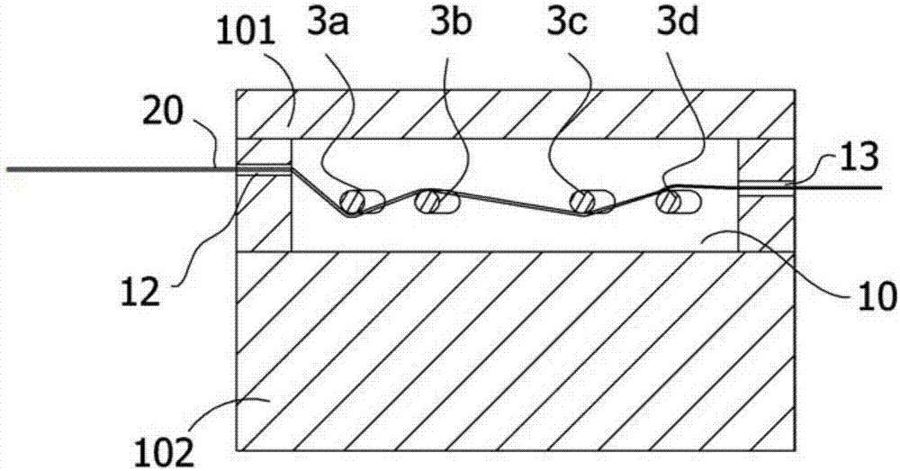
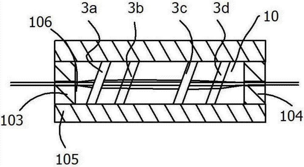
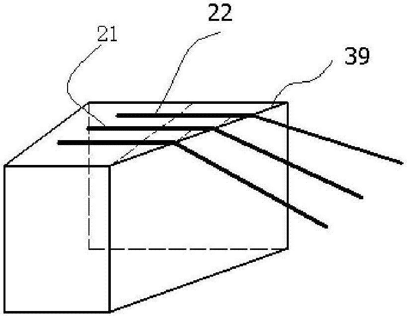
[0031] Embodiment one, see appendix Figure 1~3 , a mold for producing continuous fiber reinforced thermoplastics, comprising an upper mold base 101 and a lower mold base 102, left, right, front and rear mold walls 103, 104, 105 and 106, a mold cavity 10 is formed between the upper mold base, the lower mold base, the left mold wall, the right mold wall, the front mold wall and the rear mold wall, the left mold wall is provided with a feed channel, and the right mold wall is provided with In the discharge channel, the continuous fiber yarn bundle is fed from the left mold wall and discharged from the right mold wall; two groups of fiber dispersions are installed between the front mold wall and the rear mold wall, and each group of fiber dispersions includes two Fiber dispersion blocks, the fiber dispersion blocks are pins, and the two fiber dispersion blocks in each group are parallel to each other, and each group of fiber dispersions is parallel to or not parallel to each othe...

Embodiment 2

[0034] Embodiment two, see appendix Figure 4 and 5 , including an upper mold base and a lower mold base, left, right, front and rear mold walls are installed between the upper mold base and the lower mold base, the upper mold base, lower mold base, left mold wall, right mold wall, A mold cavity 10 is formed between the front mold wall and the rear mold wall. The left mold wall is provided with a feed channel, and the right mold wall is provided with a discharge channel. The continuous fiber yarn is fed from the left mold wall and exited from the right mold wall. material; the fiber dispersion block is 4 groups of oblique prism structures 3a', 3b', 3c', 3d', and each group of oblique prism structures is provided with a cylindrical surface in contact with the continuous fiber yarn bundle, and the lower side of the upper mold wall is installed There are two sets of oblique prism structures, and two sets of oblique prism structures are also installed on the upper side of the low...


PUM


Abstract

The invention relates to a mold for the production of continuous fiber reinforced thermoplastic plastic. The mold is characterized in that a continuous fiber yarn bundle is fed from a left mold wall and discharged from a right mold wall; two or more groups of fiber dispersion bodies are mounted in a mold cavity; each group of fiber dispersion bodies comprises two fiber dispersion blocks which are parallel to each other; all the groups of fiber dispersion bodies are parallel or unparallel to one another; the continuous fiber yarn bundle gets in contact with the sequentially-arranged fiber dispersion blocks from left to right; the surface, being in contact with each fiber dispersion block, of the continuous fiber yarn bundle is designed to be a cylindrical surface; an included angle of 0-25 degrees is formed between the axial direction of each cylindrical surface and the perpendicular direction between a front mold wall and a rear mold wall; and all fibers distributed along the width direction of the continuous fiber yarn bundle have the same traveling-passing length in the mold cavity, and are prevented from gathering when passing through the mold cavity. By adoption of the mold provided by the invention, the dispersion width of the continuous fiber yarn bundle is increased, the adjacent fibers are bent at different time, the fiber dispersion efficiency is improved, the situation that the continuous fiber yarn bundle is broken is reduced, and the production quality is improved.

Description

[0001] Technical field: [0002] The invention relates to the field of mold equipment, in particular to a mold for producing continuous fiber reinforced thermoplastics. [0003] Background technique: [0004] Long fiber reinforced thermoplastics is a high-performance material, which is a substitute for traditional short fiber reinforced plastics. Compared with the latter, the mechanical properties can be improved by 30-300%. [0005] The conventional production process of long fiber reinforced thermoplastics is: continuous reinforcing fiber yarns pass through a dipping die, merge with the molten resin from the extruder in the die cavity and are soaked by the resin, and cut into pellets of a certain length after exiting the die , the fibers are continuous along the length of the pellets, and the reinforcing fibers used can be glass fibers or carbon fibers, etc. This process can also be used to produce continuous fiber-reinforced thermoplastic rods, belts, profiles, etc. [0006...

Claims


Application Information

Patent Timeline
IPC IPC(8): B29C33/00B29C70/54
CPCB29C33/00B29C70/54
Inventor 费峡
Owner 湖州艾历克工业材料有限公司
Why Eureka
Try Eureka