Cart used for transporting heavy object upstairs

A technology for trolleys and heavy objects, applied in the field of trolleys, can solve the problems of large damage to stairs, difficult control of the impact of the latter, inconvenient use, etc., and achieve a smooth and quiet walking process

Inactive Publication Date: 2017-07-04
WUHAN UNIV OF SCI & TECH
View PDF6 Cites 0 Cited by
  • Summary
  • Abstract
  • Description
  • Claims
  • Application Information

AI Technical Summary

Problems solved by technology

The former will cause great damage to the stairs while the latter will ha

Method used


Image

  • Cart used for transporting heavy object upstairs
  • Cart used for transporting heavy object upstairs
  • Cart used for transporting heavy object upstairs

Examples


Embodiment 1

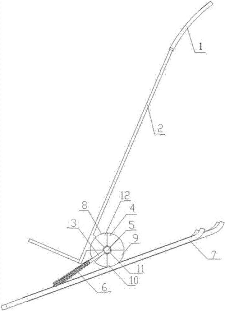
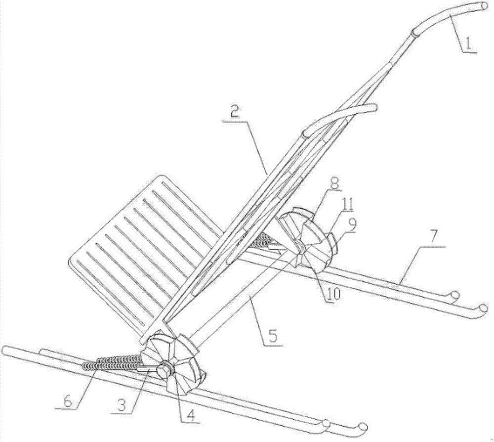
[0026] Such as figure 1 shown, combined with figure 2 and image 3 , the present invention provides a kind of trolley that is used to carry heavy object upstairs, comprises a vehicle frame 2, a wheel shaft 5, two wheels 4, two draw rings 3, four springs 6 and four cylinder rails 7. The handlebar 1 leaves room for the hand to exert force when a long object is placed. Specifically, when the length of the loaded object exceeds the length of the vehicle frame 2, the design of the handlebar 1 that forms a certain angle with the vehicle frame 2 can leave room for the hand to hold. The vehicle body includes a vehicle frame 2, a wheel shaft 5 and a handlebar 1; the wheel 4 is connected to the two ends of the wheel shaft 5 through bearings; The ring 3 is connected, and the lower end is connected with the cylindrical track 7 behind the forward direction of the wheel 4; the cylindrical track 7 is located below the wheel 4 and contacts with the stairs.

[0027] Such as Figure 4 As ...

Embodiment 2

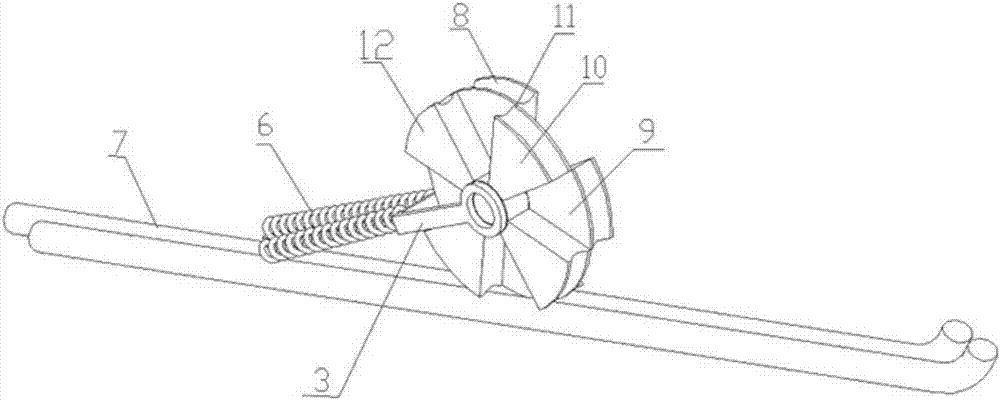
[0030] Such as Figure 5 As shown, the other structures and usage methods of Embodiment 2 are the same as Embodiment 1, the difference is that: the sector wheel plates 12 of the left wheel subsection 9 of each wheel 4 are three and evenly distributed, and the arc of each sector wheel plate 12 is 60°, and the gap between the two fan-shaped wheel plates is also just 60°. The structure of the right wheel subsection 10 is the same as that of the left wheel subsection 9, and the fan-shaped wheel plate 12 of the right wheel subsection 10 and the left wheel subsection 9 is also Alternately distributed.

Embodiment 3

[0032] Such as Figure 6 As shown, the other structures and usage methods of Embodiment 3 are the same as Embodiment 1, the difference is that: the sector wheel plates 12 of the left wheel subsection 9 of each wheel 4 are five and evenly distributed, and the arc of each sector wheel plate 12 It is 36 °, and the gap between the two fan-shaped wheel plates is also just 36 °. The structure of the right wheel subsection 10 is the same as that of the left wheel subsection 9, and the fan-shaped wheel plate 12 of the right wheel subsection 10 and the left wheel subsection 9 is also the same. Alternately distributed.


PUM

PropertyMeasurementUnit
Radiusaaaaaaaaaa
Lengthaaaaaaaaaa

Abstract

The invention discloses a cart used for transporting a heavy object upstairs. The cart comprises a cart frame, a cart wheel shaft arranged on the cart frame and two cart wheels connected with the two ends of the cart wheel shaft through bearings correspondingly; two cylindrical rails arranged below each cart wheel are connected with the cart wheel shaft through springs correspondingly, each cart wheel comprises a left cart wheel part and a right cart wheel part which are the same in structure and each composed of at least three evenly-distributed fan-shaped wheel plates, and the radian of each fan-shaped wheel plate is the same as that of the space between every two fan-shaped wheel plates; and the fan-shaped wheel plates of the left cart wheel part and the right cart wheel part are arranged in a staggered mode, namely the fan-shaped wheel plates of the left cart wheel part corresponds the space between every two fan-shaped wheel plates of the right cart wheel part, and the left cart wheel part and the right cart wheel part are tightly pressed on the two corresponding different cylindrical rails correspondingly. The cart used for transporting the heavy object upstairs is simple in structure, easy to operate and low in manufacturing cost and saves a lot of labors.

Description

technical field [0001] The invention relates to carrying heavy objects upstairs, in particular to a trolley for carrying heavy objects upstairs. Background technique [0002] It is very difficult to carry heavy objects in buildings without elevators, especially for those elderly people who have gone up, and it is almost impossible to carry heavy objects without the help of auxiliary tools. It is also extremely difficult for people to move large furniture and large appliances when moving. Existing upstairs car mainly contains crawler type and planetary wheel type. The former will cause great damage to the stairs while the latter will have a large impact and is difficult to control, so it is inconvenient to use. Contents of the invention [0003] The purpose of the patent of the present invention is to propose a kind of handcart that damages little to stairs, is simple and practical to transport heavy objects upstairs. [0004] In order to solve the problems of the te...

Claims


Application Information

Patent Timeline
IPC IPC(8): B62B5/02
CPCB62B5/025
Inventor 周爽赵慧刘访
Owner WUHAN UNIV OF SCI & TECH
Why Eureka
Try Eureka