
Base of electronic cigarette atomization device, electronic cigarette atomization device and electronic cigarette

An electronic cigarette and chemical device technology, applied in the field of electronic cigarettes, can solve the problems of little change in airflow, poor matching degree, taste deviation, etc., and achieve the effects of maintaining stable airflow, improving consistency, and adjusting matching degree.

Pending Publication Date: 2020-09-18
赵磊
View PDF0 Cites 1 Cited by
  • Summary
  • Abstract
  • Description
  • Claims
  • Application Information

AI Technical Summary

Problems solved by technology

[0003] The atomization device of the traditional electronic cigarette is usually equipped with an air inlet, a suction port, and an atomization chamber equipped with heating components. The second stage of airflow between the air guide port and the heating component and the third stage of airflow from the atomization chamber to the suction port, while the traditional atomization device usually adjusts the conduction area of ​​the air inlet to adjust the size of the airflow, while the mist The area of ​​the air guide port of the atomization chamber remains unchanged. When the air inlet adjustment range is such that the conduction area of ​​the air inlet port is larger than the area of ​​the air guide port, the airflow entering the atomization chamber per unit time does not change substantially, and the matching degree is poor.
At the same time, when the adjustment range of the air inlet is such that the conduction area of ​​the air inlet is smaller than the area of ​​the air guide port, the airflow between the air inlet and the air guide port can be drawn out quickly during suction, and the external airflow passes through the small-diameter air intake. Mouth replenishment is slow, resulting in deviations in taste before and after

Method used


Image

  • Base of electronic cigarette atomization device, electronic cigarette atomization device and electronic cigarette
  • Base of electronic cigarette atomization device, electronic cigarette atomization device and electronic cigarette
  • Base of electronic cigarette atomization device, electronic cigarette atomization device and electronic cigarette

Examples


Embodiment Construction

[0042] The following will clearly and completely describe the technical solutions in the embodiments of the present invention with reference to the accompanying drawings in the embodiments of the present invention. Obviously, the described embodiments are only part of the embodiments of the present invention, not all of them. Based on the embodiments of the present invention, all other embodiments obtained by persons of ordinary skill in the art without creative efforts fall within the protection scope of the present invention.

[0043]It should be noted that all directional indications (such as up, down, left, right, front, back...) in the embodiments of the present invention are only used to explain the relationship between the components in a certain posture (as shown in the accompanying drawings). Relative positional relationship, movement conditions, etc., if the specific posture changes, the directional indication will also change accordingly.

[0044] In addition, the d...


PUM


Abstract

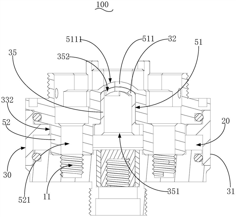
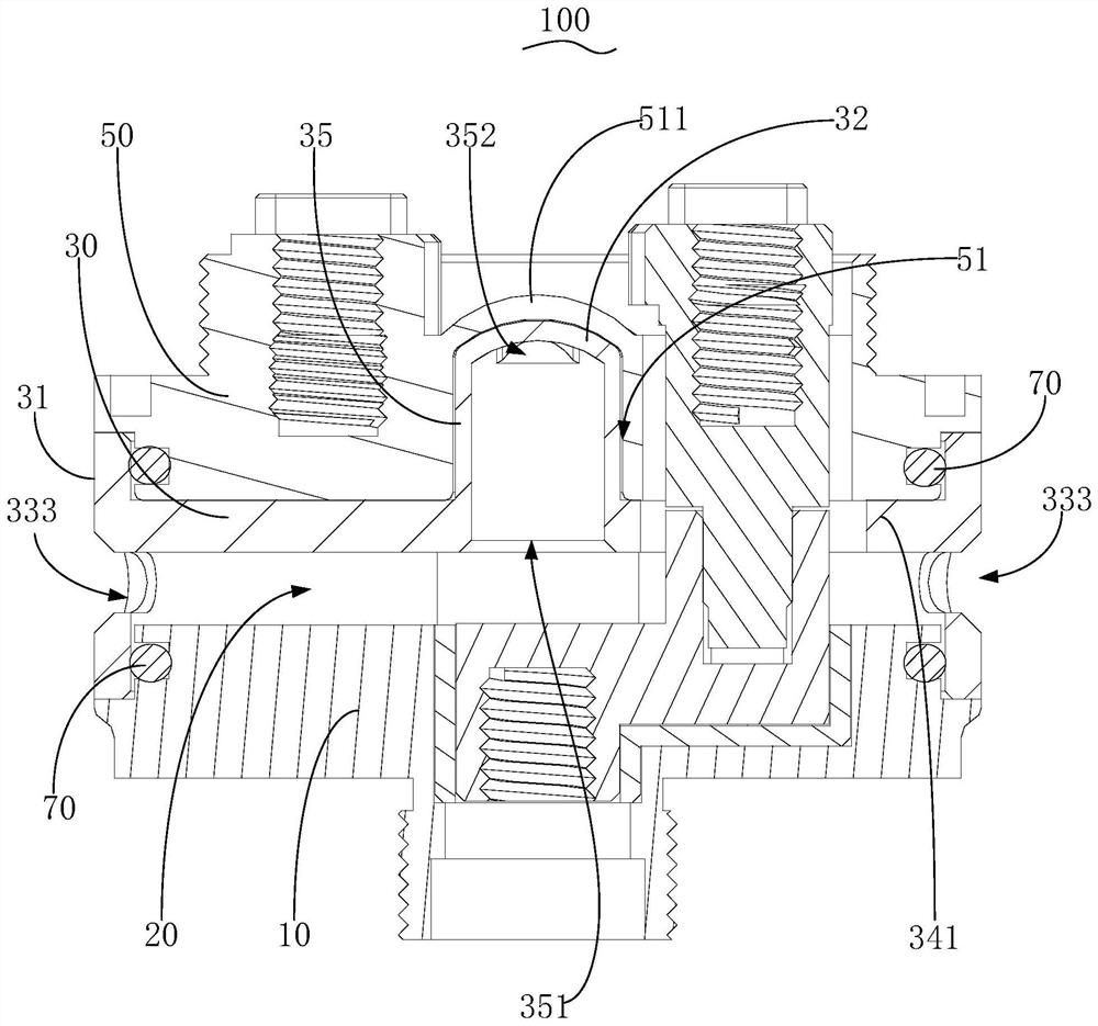
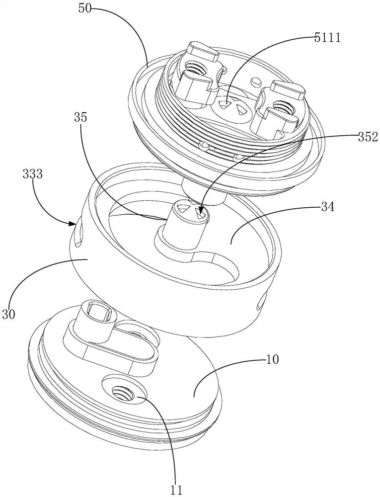
The invention provides a base of an electronic cigarette atomization device, the electronic cigarette atomization device applying the base and an electronic cigarette applying the atomization device.The base comprises a base body, a gas adjusting piece and a bearing base for installing the heating assembly, wherein the bearing base is fixedly mounted on the base body; a gas passing opening is formed corresponding to the heating assembly; the gas adjusting piece is movably installed on the base body or the bearing base, a first part of the gas adjusting piece is exposed to the outside to forma control part, a second part of the gas adjusting piece extends to cover the gas passing opening, and the control part drives the second part to move under the action of external force to adjust thegas flow conduction area of the gas passing opening. According to the base, the electronic cigarette atomization device and the electronic cigarette, the matching degree is high when the gas flow is adjusted through using the atomization device, and the taste stability is high.

Description

technical field [0001] The invention relates to a base of an electronic atomization device, an electronic atomization device using the base, and an electronic cigarette using the atomization device. Background technique [0002] Electronic cigarettes, also known as electronic cigarettes, are mainly used to quit smoking and replace traditional cigarettes. It has a similar appearance and similar taste to traditional cigarettes, and even has more flavors than traditional cigarettes. It can also suck out smoke, taste and feeling like traditional cigarettes. Because electronic cigarettes do not have other harmful components such as tar and suspended particles in traditional cigarettes, they gradually replace traditional cigarettes in the market. [0003] The atomization device of the traditional electronic cigarette is usually equipped with an air inlet, a suction port, and an atomization chamber equipped with heating components. The second stage of airflow between the air guid...

Claims


Application Information

Patent Timeline
Patent Type & Authority Applications(China)
IPC IPC(8): A24F40/40A24F40/50
CPCA24F40/40A24F40/50
Inventor 赵磊
Owner 赵磊
Learn More